Strategies for Preventing Electrode Fouling in Electrochemical Biosensors: From Materials to Clinical Applications
Electrode fouling remains a critical challenge that compromises the accuracy, reliability, and longevity of electrochemical biosensors, particularly in complex biological media like blood and serum.
Strategies for Preventing Electrode Fouling in Electrochemical Biosensors: From Materials to Clinical Applications
Abstract
Electrode fouling remains a critical challenge that compromises the accuracy, reliability, and longevity of electrochemical biosensors, particularly in complex biological media like blood and serum. This article provides a comprehensive analysis of recent scientific advances and practical strategies to mitigate fouling. It explores the fundamental mechanisms of nonspecific adsorption, showcases innovative antifouling materials such as zwitterionic peptides and engineered polymers, and details optimization techniques to enhance sensor stability. Furthermore, it critically evaluates validation protocols and performance metrics essential for translating these biosensors from research laboratories to real-world clinical, environmental, and point-of-care applications, offering researchers a structured roadmap for developing robust and fouling-resistant sensing platforms.
Understanding Electrode Fouling: Mechanisms and Impact on Biosensor Performance
In electrochemical biosensing, nonspecific adsorption (NSA) is the unintended accumulation of proteins, lipids, or other biomolecules onto an electrode surface. This phenomenon, often called "biofouling," directly passivates the electrode by forming an insulating layer that hinders electron transfer, reduces sensitivity, increases the limit of detection, and causes signal drift [1] [2]. For researchers and scientists developing robust biosensors, understanding and mitigating NSA is critical to obtaining reliable data, especially when working with complex biological samples like blood, serum, or in vivo environments [3] [2]. This guide provides troubleshooting and foundational knowledge to address this fundamental challenge.
FAQ: Understanding and Detecting Nonspecific Adsorption
Q1: What are the primary mechanisms behind nonspecific adsorption? NSA is primarily driven by a combination of physical and chemical interactions between the sensor surface and components in the sample matrix [2]. The main forces include:
- Electrostatic interactions between charged electrode surfaces and ions or charged molecules in the solution.
- Hydrophobic interactions, which are a major driving force for the adsorption of proteins and lipids.
- Hydrogen bonding and other dipole-dipole interactions.
- van der Waals forces [2]. In complex samples like serum, proteins such as albumin readily adsorb to surfaces, creating a fouling layer that can either mask the signal from the target analyte or block the bioreceptor's ability to bind its target, leading to false negatives [2].
Q2: How can I experimentally confirm that my electrode is passivated? A combination of electrochemical and physical techniques can confirm electrode passivation:
- Electrochemical Impedance Spectroscopy (EIS): A significant increase in charge transfer resistance (( R_{ct} )) is a classic indicator of electrode passivation.
- Cyclic Voltammetry (CV): A decrease in the peak current and an increase in the peak-to-peak separation for a redox probe like ( [Fe(CN)_6]^{3-/4-} ) suggest a fouled surface.
- Surface Plasmon Resonance (SPR): When coupled with electrochemistry (EC-SPR), this technique can directly monitor the accumulation of mass on the electrode surface in real-time, providing unambiguous evidence of fouling [2].
The following workflow outlines a systematic approach for diagnosing electrode passivation:
Q3: Why does passivation cause signal drift in continuous monitoring? Signal drift occurs because NSA is often a dynamic and progressive process. As non-target molecules slowly but continuously adsorb onto the electrode surface, they create an increasing barrier to electron transfer [2]. This leads to a steadily decaying signal over time, even if the concentration of the target analyte remains constant. In in vivo sensors, this is compounded by the foreign body response, which can lead to glial cell activation and fibrotic encapsulation of the electrode [1].
Troubleshooting Guide: Solutions to Prevent and Mitigate Passivation
Antifouling Materials and Coatings
A primary strategy to combat NSA is to functionalize the electrode surface with antifouling materials that create a physical and energetic barrier against non-specific interactions.
Table 1: Common Antifouling Materials for Electrochemical Biosensors
| Material Category | Examples | Mechanism of Action | Key Characteristics |
|---|---|---|---|
| Polymeric Films | Nafion [1], Zwitterionic polymers [1], Polydopamine (PDA) [1] | Creates a hydrophilic, neutral, or negatively charged barrier that resists protein adsorption. | High hydrophilicity; can be cross-linked; some (e.g., Nafion) are permselective. |
| Biomimetic Coatings | Natural cell membranes [1], Tannic acid (TA) [1], Cross-linked protein films [2] | Mimics biological surfaces to reduce recognition by fouling agents. | Good biocompatibility; can be complex to fabricate. |
| Nanoporous Layers | Silica nanoporous membrane (SNM) [1], Mesoporous gold membrane (mAu) [1] | Provides size exclusion and reduces the available surface area for fouling. | High surface area; can be tuned for specific pore sizes. |
| Hybrid Materials | CNT-conducting polymer composites [1], Peptide-based coatings [2] | Combines multiple antifouling mechanisms (e.g., conductivity and hydrophilicity). | Tunable properties; can be designed for high-performance. |
Experimental Protocol: Coating an Electrode with a Zwitterionic Polymer for Antifouling
This protocol outlines the steps for creating a robust antifouling layer using a zwitterionic polymer on a gold electrode.
Principle: Zwitterionic polymers possess both positive and negative charges, creating a highly hydrophilic surface that strongly binds water molecules. This formed hydration layer creates a physical and energetic barrier that prevents proteins from adsorbing and denaturing on the surface [1] [2].
Materials:
- Working Electrode: Gold disk electrode (2 mm diameter).
- Cleaning Reagents: Piranha solution (Caution: Highly corrosive!), absolute ethanol.
- Polymer Solution: 1 mg/mL solution of a zwitterionic polymer (e.g., poly(sulfobetaine methacrylate) in deionized water.
- Cross-linker: 10 mM EDC (1-Ethyl-3-(3-dimethylaminopropyl)carbodiimide) and 5 mM NHS (N-Hydroxysuccinimide) in MES buffer (pH 6.0).
- Testing Solutions: 10 mM ( [Fe(CN)_6]^{3-/4-} ) in 1X PBS, 10% (v/v) Fetal Bovine Serum (FBS) in PBS.
Procedure:
- Electrode Pretreatment:
- Polish the gold electrode with 0.3 µm and 0.05 µm alumina slurry sequentially on a microcloth. Rinse thoroughly with deionized water after each polish.
- Clean the electrode by cycling in 0.5 M ( H2SO4 ) between -0.2 V and +1.5 V (vs. Ag/AgCl) until a stable cyclic voltammogram characteristic of a clean Au surface is obtained.
- Rinse with copious amounts of deionized water and dry under a stream of ( N_2 ) gas.
Surface Functionalization:
- Immerse the clean, dry electrode in the polymer solution for 2 hours at room temperature to allow physical adsorption.
- For a more stable covalent layer, subsequently immerse the electrode in the EDC/NHS cross-linking solution for 1 hour to activate carboxyl groups on the polymer.
- Rinse the modified electrode gently with deionized water to remove any loosely bound polymer.
Antifouling Performance Evaluation:
- Characterize the modified electrode using CV and EIS in the ( [Fe(CN)_6]^{3-/4-} ) solution to establish a baseline.
- Incubate the electrode in 10% FBS for 1 hour at 37°C to simulate a fouling challenge.
- Rinse the electrode with PBS and re-measure the CV and EIS in the ( [Fe(CN)_6]^{3-/4-} ) solution.
- A successful coating will show minimal change (< 10%) in the ( R_{ct} ) and peak current after FBS incubation compared to the baseline.
Alternative Sensing Mechanisms to Bypass Fouling
Innovative sensing mechanisms can inherently reduce the impact of fouling:
- Galvanic Redox Potentiometry (GRP): This method replaces the conventional current signal with a potential output, which is less susceptible to the resistive effects of a fouling layer [1].
- Organic Electrochemical Transistors (OECTs): In an OECT, the sensing signal is transconductance (( g_m )), which is based on volumetric ion doping of a channel. This mechanism is less affected by surface fouling compared to traditional electrodes that rely on direct electron transfer at the surface [1].
The Scientist's Toolkit: Key Research Reagents & Materials
Table 2: Essential Reagents for Developing Antifouling Electrochemical Biosensors
| Reagent/Material | Function | Example Use Case |
|---|---|---|
| Carbon Fiber Microelectrode | The foundational working electrode; offers excellent spatio-temporal resolution for in vivo studies. | Baseline electrode for neurochemical sensing (e.g., dopamine detection) [1]. |
| Nafion Perfluorinated Resin | A cation-exchange polymer used as an antifouling and permselective membrane. | Coating for in vivo microelectrodes to repel negatively charged interferents like ascorbic acid [1]. |
| EDC & NHS Cross-linkers | Activate carboxyl groups for covalent immobilization of biomolecules and polymers. | Creating stable, covalently bound antifouling layers (e.g., with zwitterionic polymers) [2]. |
| Zwitterionic Polymer (e.g., PSBMA) | Forms a super-hydrophilic surface that resists protein adsorption via a strong hydration layer. | Gold electrode coating for sensing in blood serum [1] [2]. |
| Fetal Bovine Serum (FBS) | A complex matrix of proteins and lipids used to simulate biofouling conditions. | Standard solution for challenging and validating antifouling coatings in vitro [2]. |
| Potassium Ferrocyanide/Ferricyanide | A standard redox probe for characterizing electrode kinetics and surface fouling. | Used in CV and EIS to monitor changes in electron transfer efficiency before/after fouling challenges. |
FAQs: Understanding and Troubleshooting Electrode Fouling
FAQ 1: What are the primary causes of performance degradation in electrochemical biosensors used in complex biological fluids like blood and serum? The primary cause is electrode biofouling, a process where nonspecific substances in the sample adsorb onto the electrode surface. In serum and blood, the key interferents are proteins, lipids, and cells [4] [5]. This fouling occurs in stages: an initial layer of molecules forms instantly, followed by the main layer of foulants, which can then grow into biofilms and lead to macrofouling over days or weeks [4]. This fouling layer physically blocks the sensing pathway, passivates the electrode, and significantly reduces the sensor's accuracy, sensitivity, and functionality [6] [5].
FAQ 2: Besides fouling, what other interferents affect biosensor accuracy in these fluids? Beyond the fouling from proteins and lipids, a major class of interferents is redox-active compounds [7]. In serum, these can include endogenous molecules like ascorbate (ascorbic acid), uric acid, and acetaminophen [7]. These compounds can be oxidized or reduced at the electrode surface at similar potentials to the target analyte, generating a false current signal and leading to inaccurate measurements.
FAQ 3: What material properties are crucial for creating an antifouling sensor interface? Hydrophilicity is a key property. Research has shown that superhydrophilic surfaces create a robust hydration layer that minimizes the adhesion of biomolecules [6]. Zwitterionic materials, which contain both positive and negative charges, are also highly effective as they form strong hydration layers via electrostatic interactions, providing superior resistance to protein adsorption [8]. The three-dimensional branched architecture of dendritic zwitterionic oligopeptides can form more intramolecular hydrogen bonds, leading to a more stable hydration layer and superior antifouling capability compared to linear versions [8].
FAQ 4: My sensor works perfectly in buffer but fails in real samples. What are the first things I should check? This is a classic symptom of fouling or interference. Your troubleshooting checklist should include:
- Antifouling Coating: Does your electrode have a dedicated antifouling layer (e.g., hydrogel, zwitterionic peptide, permselective polymer)?
- Physical Barrier: For wearable sensors, have you considered a microfluidic channel to physically block contaminants from the skin? [6]
- Interferent Rejection: Does your sensor design include a permselective membrane (e.g., non-conducting polymers like poly(o-phenylenediamine)) to filter out redox-active species? [7]
- Detection Potential: Can you lower the operational potential of your sensor to avoid the oxidation window of common interferents? [7]
Comparison of Antifouling and Interference-Rejection Strategies
The table below summarizes quantitative data and key characteristics of various strategies discussed in recent literature for mitigating fouling and interference.
Table 1: Comparison of Advanced Antifouling and Interference-Rejection Strategies
| Strategy / Material | Key Characteristics | Target Interferents | Performance Highlights |
|---|---|---|---|
| Superhydrophilic MOF (Cu-HHTP) [6] | Conductive metal-organic framework (MOF) with tuned hydrophilic surface. | Lipids in sweat | Prevents lipid buildup; enables accurate real-time monitoring for 24 h. |
| Double-Conductive Hydrogel (KMPPH) [5] | Hydrogel incorporating MXene and PEDOT:PSS for conductivity and stability. | Proteins, polysaccharides, lipids in serum | Low detection limit of 0.41 pg/mL for CEA in serum; good stability. |
| Dendritic Zwitterionic Oligopeptide (EK(E)CE(K)K) [8] | 3D branched peptide structure with alternating glutamic acid and lysine. | Proteins in saliva, sweat, blood | Forms 8 intramolecular H-bonds; superior hydrophilicity and stable hydration vs. linear peptides. |
| All-Electrochemical Biosensor Assembly [7] | Combines electrophoretic enzyme deposition with electrosynthesized permselective polymers. | Electroactive species (e.g., ascorbate, uric acid), proteins | Low interference bias (low µM range); successful glucose determination in untreated serum. |
| Conductive Membrane [9] | Membrane that allows analyte passage but electrochemically deactivates interferents. | Redox-active interferents | Selectively blocks redox-active interferents while allowing target analyte to pass. |
Detailed Experimental Protocols
This protocol describes creating an electrode where the antifouling property is intrinsic to the sensing material.
- Key Reagent: Precursor solution of the conductive MOF Cu-HHTP (copper hexahydroxytriphenylene).
- Procedure:
- Substrate Preparation: Clean and prepare a flexible substrate suitable for your application.
- Inkjet Printing: Load the precursor solution (containing metal salts and organic ligands) into an inkjet printer.
- MOF Formation: Print the precursor solution onto the substrate. The MOF electrodes form through an in-situ self-assembly process as the solvent evaporates. This method ensures a strong bond between the MOF and the substrate.
- Mechanism of Action: The resulting Cu-HHTP electrode is superhydrophilic, exhibiting low surface energy that minimizes lipid adhesion. This prevents the formation of an inhomogeneous fouling layer, maintaining a stable current signal over time.
This protocol involves creating a separate, multifunctional hydrogel layer that provides both antifouling and conductive properties.
- Key Reagents: MXene nanosheets (conductive framework), KH570 (coupling agent), PEDOT:PSS (conductive polymer), [Ru(NH3)6]3+ (internal standard).
- Procedure:
- Synthesize MXene-COOH-Ru: Prepare single-layer MXene nanosheets via etching of Ti3AlC2. Then, carboxylate the MXene and load it with [Ru(NH3)6]3+.
- Form the Hydrogel (KMPPH): Mix the MXene-COOH-Ru complex with KH570 and PEDOT:PSS. This forms a stable, double-conductive antifouling hydrogel.
- Modify the Electrode: Cast the KMPPH hydrogel onto the surface of your electrochemical electrode (e.g., glassy carbon electrode).
- Immobilize Recognition Element: Attach the appropriate capture aptamers to the hydrogel surface for specific target detection (e.g., for carcinoembryonic antigen, CEA).
- Mechanism of Action: The hydrogel's superhydrophilicity creates a physical barrier that repels proteins, polysaccharides, and lipids. Its dual conductivity ensures efficient electron transfer, while the encapsulated [Ru(NH3)6]3+ serves as an internal standard for a ratiometric sensing strategy, correcting for background signals and instrument errors.
This protocol uses electrochemical methods to sequentially deposit a permselective polymer and immobilize enzymes, ideal for creating well-defined, miniaturized sensors.
- Key Reagents: Enzyme (e.g., Glucose Oxidase), Bovine Serum Albumin (BSA), Glutaraldehyde (GLU), Monomer for electrosynthesis (e.g., o-phenylenediamine, pyrrole).
- Procedure:
- Electrosynthesize the Permselective Polymer: Using cyclic voltammetry (CV), electrosynthesize a non-conducting polymer (e.g., poly(o-phenylenediamine)) from its monomer directly onto the Pt working electrode surface. This forms a thin, dense film.
- Electrophoretic Protein Deposition (EPD): Place the polymer-coated electrode in a solution containing the enzyme, BSA, and GLU.
- Apply Electrical Field: Apply a pulsed current sequence. This causes the electrophoretic migration of the enzyme and BSA to the electrode surface, triggering in-situ co-crosslinking exclusively onto the electrode.
- Mechanism of Action: The electrosynthesized polymer acts as a size-exclusion and charge-selective membrane, rejecting common interferents like ascorbate and uric acid. The EPD step ensures precise spatial control of enzyme immobilization. This combined approach yields a biosensor with high enzyme loading, excellent interferent rejection, and good shelf lifetime.
Experimental Workflow for Antifouling Biosensor Development
The following diagram illustrates a generalized logical workflow for developing and troubleshooting an electrochemical biosensor for complex fluids, integrating the strategies discussed above.
The Scientist's Toolkit: Key Research Reagent Solutions
Table 2: Essential Materials for Antifouling Biosensor Research
| Category | Reagent / Material | Function in Experimental Design |
|---|---|---|
| Advanced Materials | Conductive MOFs (e.g., Cu-HHTP) [6] | Serves as both the sensing electrode and antifouling layer via tuned superhydrophilicity. |
| MXene Nanosheets [5] | Acts as a highly conductive nanomaterial framework within hydrogels, providing large surface area. | |
| Conductive Polymers (e.g., PEDOT:PSS, Polyaniline) [10] [5] | Imparts electrical conductivity to hydrogels and other polymer matrices. | |
| Antifouling Polymers & Peptides | Zwitterionic Peptides (e.g., dendritic EK(E)CE(K)K) [8] | Forms a strong hydration layer via electrostatic interactions to prevent protein adsorption. |
| Non-Conducting Polymers (e.g., poly(o-phenylenediamine)) [7] | Electrosynthesized to form thin, permselective films that reject interferents. | |
| Polyethylene Glycol (PEG) & Derivatives [5] | Traditional hydrophilic polymer used to create antifouling surfaces. | |
| Hydrogels | Double-Conductive Hydrogels (e.g., KMPPH) [5] | Combines superhydrophilic antifouling properties with high conductivity for enhanced signal. |
| Polyaniline (PANI) Hydrogel [10] | Provides a 3D antifouling interface with water retention capabilities and inherent conductivity. | |
| Assembly & Immobilization | Electrophoretic Protein Deposition (EPD) [7] | An electrochemically assisted technique for precise, spatially controlled enzyme immobilization. |
| γ-Methacryloxypropyltrimethoxysilane (KH570) [5] | A coupling agent used to improve the stability and adhesion of materials to surfaces. |
Electrode fouling is a critical challenge in electrochemical biosensing, where the non-specific adsorption of proteins, cells, lipids, and other biomolecules onto the electrode surface occurs during exposure to complex biological fluids like blood, serum, or saliva [11] [12] [13]. This process creates an impermeable layer that degrades sensor performance by reducing sensitivity, impairing specificity, and shortening operational lifespan [12]. In blood, for instance, proteins such as human serum albumin (HSA), IgG, and fibrinogen are primarily responsible for surface fouling, leading to a drastic decrease in analytical performance [11]. Overcoming biofouling is essential for developing reliable biosensors for clinical diagnostics, therapeutic drug monitoring, and long-term implantable devices [14].
Frequently Asked Questions (FAQs)
Q1: What are the primary consequences of electrode fouling on my electrochemical biosensor's performance?
Electrode fouling directly impacts three key performance parameters:
- Reduced Sensitivity: The fouling layer acts as a physical and chemical barrier, impeding the diffusion of the target analyte to the electrode surface and the subsequent electron transfer. This leads to a diminished electrochemical signal [12] [15].
- Loss of Specificity: Non-specific adsorption of interfering molecules can produce a false positive signal or mask the signal from the true target, leading to inaccurate readings [13].
- Shortened Sensor Lifespan: The accumulation of fouling agents can permanently deactivate the electrode's catalytic sites or immobilized bioreceptors. In implantable sensors, this is compounded by the foreign body response, which can encapsulate the device in fibrotic tissue, rendering it useless [14].
Q2: In complex biofluids like blood, which components are most responsible for fouling?
Blood is a particularly challenging matrix. The main components responsible for fouling are plasma proteins [11]:
- Human Serum Albumin (HSA): Comprises ~60% of total plasma proteins (35–50 mg mL⁻¹).
- Immunoglobulin G (IgG): Present at 6–16 mg mL⁻¹.
- Fibrinogen: Found at concentrations around 2 mg mL⁻¹. These proteins adsorb onto metallic surfaces like gold electrodes through hydrophobic interactions and electrostatic forces, forming a tenacious fouling layer [11].
Q3: My sensor signal degrades within hours in cell culture medium. What are some proven antifouling strategies I can implement?
Multiple strategies have been developed to mitigate fouling. The choice depends on your sensor design and application. The table below summarizes solutions validated in complex environments.
Table 1: Comparison of Key Antifouling Strategies for Electrochemical Sensors
| Strategy | Key Materials | Mechanism of Action | Reported Performance | Key Considerations |
|---|---|---|---|---|
| Hydrophilic Polymer Brushes | PEG/OEG, Zwitterionic polymers [11] [16] [13] | Forms a hydrated layer via steric repulsion and water binding to prevent protein adhesion [11] [12]. | Zwitterionic coatings enhance continuous sensing for therapeutic drug monitoring [16]. | PEG can be susceptible to oxidative degradation; zwitterions offer higher stability [12] [13]. |
| Protein-Based Nanocomposite | Cross-linked Bovine Serum Albumin (BSA) with Gold Nanowires [14] [17] | Creates a natural physical barrier and incorporates conductive elements to maintain electron transfer [17]. | Maintains electron transfer kinetics for over one month in serum and nasopharyngeal secretions [17]. | Nozzle printing allows for precise, localized deposition on working electrodes [17]. |
| Antifouling Peptides | Self-assembled peptide nanoparticles (e.g., FFFGGGEKEKEKEK) [18] | Provides a stable, biocompatible interface resistant to non-specific adsorption and enzymatic hydrolysis [18]. | Enables accurate biomarker detection in complex biofluids [18]. | Designed for enhanced stability against proteolytic degradation in biological fluids. |
| Porous & Nanostructured Layers | Nanoporous gold, sol-gel silicate, porous emulsions [11] [12] [17] | Acts as a diffusion filter, blocking large fouling agents (proteins, cells) while allowing small analyte access [11]. | Porous gold electrodes reduce fouling; silicate sol-gel preserved signal after 6 weeks in cell culture [12]. | Porosity and thickness are critical for balancing antifouling and mass transport [17]. |
Q4: Are there any antifouling coatings that also maintain good electron transfer kinetics?
Yes, this is a key area of advancement. Conductive antifouling coatings are ideal. A prominent example is the micrometer-thick porous nanocomposite made from cross-linked BSA and gold nanowires (AuNWs) [17]. The BSA matrix provides excellent antifouling properties, while the embedded AuNWs create efficient electron transfer pathways, ensuring high sensor sensitivity even in fouling environments for extended periods [17].
Experimental Protocols for Validation and Troubleshooting
Protocol 1: Evaluating Antifouling Performance in Complex Media
This protocol is adapted from methods used to test long-term stability in biological fluids [12] [17].
Objective: To assess the effectiveness of an antifouling coating by monitoring the stability of an electrochemical signal in a complex, fouling medium over time.
Materials:
- Electrochemical workstation
- Modified working electrode (with your sensor and antifouling coating)
- Reference electrode (e.g., Ag/AgCl) and counter electrode (e.g., Pt wire)
- Cell culture medium (e.g., DMEM with 10% FBS) or human serum/plasma
- Phosphate Buffered Saline (PBS), pH 7.4
Procedure:
- Baseline Measurement: In a clean PBS solution, perform a cyclic voltammetry (CV) or electrochemical impedance spectroscopy (EIS) measurement to record the baseline signal of your redox probe or mediator.
- Incubation: Immerse the modified working electrode in the cell culture medium or serum. Maintain it at 37°C to simulate physiological conditions.
- Periodic Testing: At predetermined time points (e.g., 1h, 6h, 24h, 72h, 1 week), remove the electrode, rinse gently with PBS, and perform the same electrochemical measurement in a fresh PBS solution.
- Data Analysis: Compare the peak current (for CV) or charge transfer resistance (for EIS) at each time point to the initial baseline. A stable signal indicates effective antifouling protection, while a decaying signal indicates fouling.
Protocol 2: Fabrication of a Conductive Albumin-Based Nanocomposite Coating
This protocol summarizes the innovative method for creating a highly effective, thick antifouling coating [17].
Objective: To create a micrometer-thick, porous, and conductive antifouling coating on a gold electrode using nozzle printing.
Materials:
- Gold electrode array
- Bovine Serum Albumin (BSA)
- Gold Nanowires (AuNWs)
- Hexadecane (oil phase)
- Phosphate Buffered Saline (PBS)
- Glutaraldehyde (GA)
- Nozzle printer
Workflow:
- Emulsion Preparation: Create an oil-in-water emulsion by sonicating a mixture of hexadecane (oil phase) and a PBS solution containing BSA and AuNWs (water phase) for 25 minutes to form stable, nanoscale oil droplets.
- Cross-linking: Add glutaraldehyde to the emulsion immediately before printing to initiate protein cross-linking.
- Nozzle Printing: Use a nozzle printer to deposit the emulsion precisely onto the working electrode(s) of the gold array.
- Curing and Evaporation: Heat the printed electrode to complete the cross-linking of the BSA matrix and evaporate the hexadecane oil. This process results in a ~1 µm thick coating with interconnected pores and embedded AuNWs.
The Scientist's Toolkit: Key Research Reagent Solutions
Table 2: Essential Materials for Antifouling Electrochemical Sensor Research
| Reagent/Material | Function in Antifouling Research | Example Application |
|---|---|---|
| Poly(ethylene glycol) (PEG) & Derivatives | Forms hydrophilic, steric-repulsion layers to reduce protein adsorption [11] [12]. | Creating SAMs or polymer brushes on gold electrodes. |
| Zwitterionic Compounds | Provides a super-hydrophilic surface via a tightly bound water layer, offering excellent antifouling and stability [16] [13]. | Coating for continuous sensing applications in serum [16]. |
| Bovine Serum Albumin (BSA) | Serves as a base for a biocompatible, cross-linked matrix that resists non-specific binding [14] [17]. | Key component in conductive nanocomposite coatings. |
| Gold Nanowires (AuNWs) | Integrated into non-conductive coatings to provide electrical conductivity and enhance electron transfer [17]. | Creating conductive pathways within a BSA-based coating. |
| Antifouling Peptides | Self-assemble into stable nanoparticles that create a bio-inert interface on the sensor [18]. | Forming a stable, enzyme-resistant coating for biosensors in biofluids. |
| Sol-Gel Silicate | Forms a porous, inorganic layer that acts as a physical barrier to large fouling molecules [12]. | Long-term protection of sensors in cell culture media. |
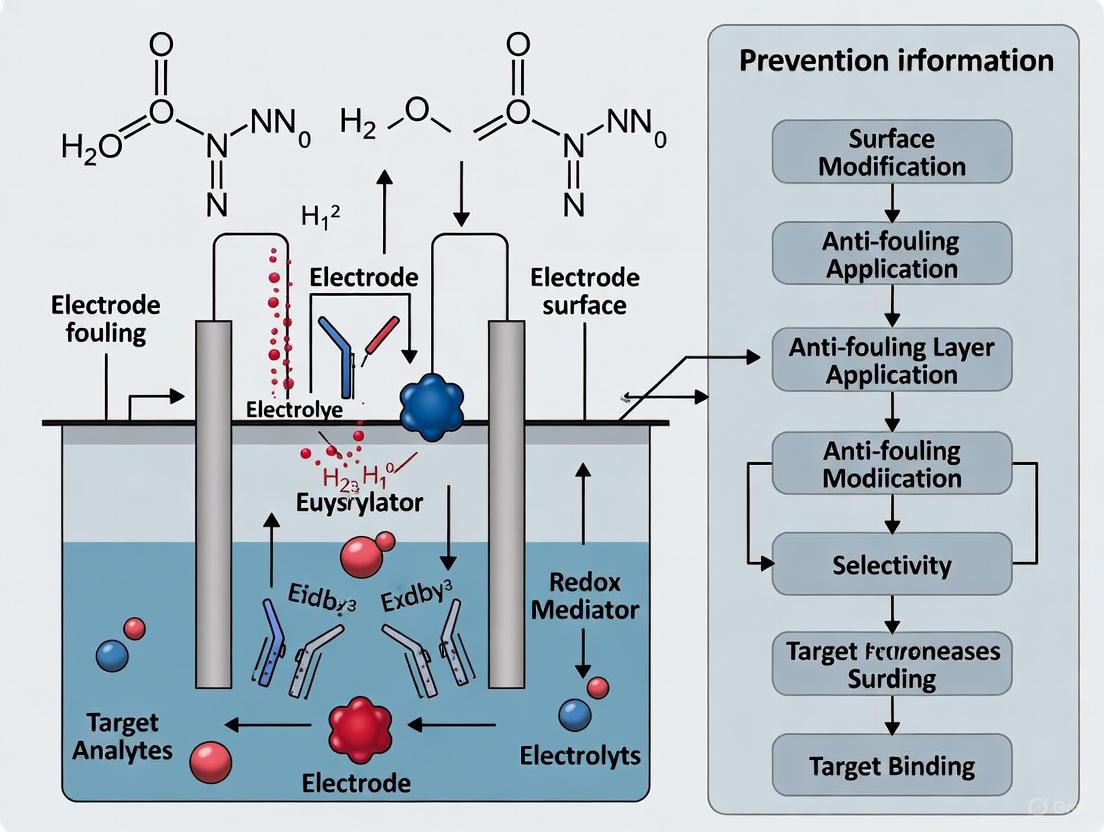
Visual Guide: Fouling Mechanisms and Antifouling Strategies
The following diagram illustrates the core problem of fouling and how different classes of antifouling strategies work to mitigate it.
Frequently Asked Questions (FAQs) & Troubleshooting Guides
Q1: What are the fundamental principles behind creating an antifouling electrochemical interface? The core principles are hydrophilicity and electroneutrality [19]. A hydrophilic surface forms a strong hydration layer via hydrogen bonding with water molecules, creating a physical and energetic barrier that repels biomolecules [11] [20]. Electroneutrality prevents charged non-target molecules from being electrostatically attracted to the sensor surface, thereby avoiding nonspecific adsorption [19]. Most fouling in biological fluids is driven by hydrophobic and electrostatic interactions; these two principles directly counteract those forces [21].
Q2: My sensor's sensitivity drops significantly after testing in serum. What is the most likely cause? This is a classic symptom of biofouling. Complex biofluids like serum contain abundant proteins (e.g., human serum albumin, IgG, fibrinogen), lipids, and other biomolecules that nonspecifically adsorb onto your electrode surface [11]. This forms an impermeable layer that blocks the target analyte from reaching the electrode, reducing electron transfer and causing signal degradation [21] [20]. To confirm, try running a control experiment with a standard redox probe in buffer before and after exposure to serum.
Q3: I am using a PEG-based antifouling layer, but my sensor's performance still degrades over time. Why? While PEG is considered the "gold standard," it has limitations. PEG chains can be susceptible to oxidative damage in biochemically relevant solutions, which compromises their long-term stability [20]. Furthermore, if the surface packing density of PEG is too low or the polymer chains are too short, the coverage may be insufficient to prevent fouling effectively [20]. Consider exploring alternative materials like zwitterionic polymers, which form a more robust hydration layer and have higher oxidative stability [20].
Q4: How can I maintain good electron transfer while having a protective antifouling layer? This is a key challenge, as thick, non-conductive polymer layers can increase impedance. Here are several strategies:
- Use conductive polymers: Integrate your antifouling strategy with conducting polymers like PEDOT:PSS or polyaniline (PANI), which provide both conductivity and fouling resistance [22] [20].
- Employ nanostructured electrodes: Materials like nanoporous gold or carbon nanotubes provide a high surface area and can act as diffusion filters, excluding large fouling proteins while allowing small analytes to pass [11] [23].
- Separate recognition and readout: Perform the immunoreaction on antifouling-modified magnetic beads. After washing, the beads are brought to the electrode for signal measurement, preventing the complex sample from ever contacting the electrode [22].
Q5: The analyte I want to detect is itself a fouling agent (e.g., dopamine). What strategies can I use? When the analyte or its reaction products foul the electrode, standard barrier methods may fail. In this case, consider:
- Electrochemical activation: Applying a specific potential waveform to desorb the fouling products between measurements [12] [21].
- Catalytic redox couples: Using mediators that shuttle electrons without the analyte itself needing to be oxidized/reduced at the electrode surface [20].
- Surface modification with specific materials: Coatings like Nafion or certain carbon materials can be selected for their ability to repel the specific polymeric fouling products, such as those generated from dopamine oxidation [21].
Research Reagent Solutions: Essential Materials for Antifouling Interfaces
The table below summarizes key materials used to construct antifouling electrochemical biosensors, based on the principles of hydrophilicity and electroneutrality.
Table 1: Key Reagents for Constructing Antifouling Interfaces
| Reagent Category | Specific Examples | Primary Function in Antifouling Design |
|---|---|---|
| Hydrophilic Polymers | Poly(ethylene glycol) (PEG), Oligo(ethylene glycol) (OEG) [11] [22] | Forms a hydrated layer via hydrogen bonding; steric repulsion of biomolecules. |
| Zwitterionic Materials | Phosphorylcholine (PC), Carboxybetaine (CB), Sulfobetaine (SB) [23] [20] | Creates a super-hydrophilic surface with a strong bound water layer; electrically neutral. |
| Conducting Polymers | Poly(3,4-ethylenedioxythiophene) (PEDOT), Polyaniline (PANI) [22] [20] | Provides electrical conductivity while can be engineered with antifouling properties. |
| Hydrogels | Chitosan hydrogel, DNA hydrogel, Peptide hydrogel [22] [19] | Highly hydrated 3D network that acts as a physical and chemical barrier to fouling agents. |
| Nanostructured Materials | Nanoporous gold, Carbon Nanotubes (CNTs) [11] [23] | Acts as a size-exclusion diffusion filter; high surface area can improve sensitivity. |
| Stable Surface Linkers | Pt-S interaction (vs. traditional Au-S) [24] | Provides a more robust anchor for biorecognition elements in complex biological fluids. |
Experimental Protocols & Workflows
Protocol 1: Constructing a Chitosan-DNA Dual-Network Hydrogel Biosensor
This protocol details the creation of a bifunctional hydrogel that combines antifouling properties with biomolecular recognition for detecting targets like ATP in complex biofluids [19].
1. Reagents and Materials:
- Chitosan (CS)
- Epichlorohydrin (ECH)
- DNA strands (Y1, Y2, Y3) and ATP-specific aptamer Linker DNA
- Hydrochloric acid (HCl) and Sodium hydroxide (NaOH)
- Glassy Carbon Electrode (GCE)
2. Step-by-Step Methodology:
- Step 1: Preparation of Y-DNA Scaffold
- Mix DNA strands Y1, Y2, and Y3 in a 1:1:1 ratio to a final concentration of 10 µM.
- Heat the mixture to 95 °C for 5 minutes to denature the DNA.
- Slowly cool the solution to room temperature to allow the self-assembly of the Y-DNA scaffold [19].
- Step 2: Electrochemical Deposition of Chitosan Hydrogel
- Prepare a 1.2 wt% CS solution dissolved in 0.46% (v/w) HCl.
- Add NaOH to a final concentration of 0.06 M and ECH to 0.04 M to the CS solution under stirring.
- Transfer the mixture to an electrochemical cell with a GCE as the working electrode.
- Apply a constant potential of -2.0 V for 120 seconds to deposit the CS hydrogel onto the GCE (CS/GCE) [19].
- Step 3: Assembly of the DNA Network
- Dropcast the prepared Y-DNA scaffold solution onto the CS/GCE surface.
- Incubate to allow the Y-DNA to attach to the CS hydrogel via electrostatic interactions and physical entanglement.
- Subsequently, introduce the Linker DNA (with the ATP aptamer) to hybridize with the Y-DNA scaffold, forming the final CS-DNA dual-network hydrogel [19].
- Step 4: Electrochemical Measurement
- Use electrochemical impedance spectroscopy (EIS) or differential pulse voltammetry (DPV) to measure the signal change upon ATP binding.
- The sensor can be tested in complex media like undiluted human serum to validate its antifouling performance [19].
The following diagram illustrates the experimental workflow and the structure of the resulting dual-network hydrogel:
Protocol 2: Fabricating a Pt-S Bond-Based Stable Antifouling Interface
This protocol describes an immobilization strategy using a robust Pt-S bond to anchor antifouling peptides, offering superior stability over conventional Au-S bonds [24].
1. Reagents and Materials:
- Platinum Nanoparticles (PtNP)
- Trifunctionalized Branched-Cyclopeptide (TBCP)
- Phosphate Buffered Saline (PBS)
2. Step-by-Step Methodology:
- Step 1: Surface Preparation with PtNPs
- Deposit platinum nanoparticles onto the clean electrode surface to serve as the platform for Pt-S bond formation [24].
- Step 2: Immobilization via Pt-S Bond
- Incubate the PtNP-modified electrode with the thiol-containing TBCP solution.
- The strong Pt-S bond forms spontaneously, securely anchoring the peptide to the surface. Electrochemical and DFT studies confirm the superior stability of Pt-S compared to Au-S bonds [24].
- Step 3: Validation of Antifouling and Stability
- Test the antifouling performance by exposing the modified electrode to undiluted human serum and monitoring the signal.
- For stability tests, perform electrochemical desorption experiments in KOH or monitor signal retention over several weeks. Electrodes with Pt-S bonds have demonstrated less than 10% signal degradation over 8 weeks [24].
Performance Data & Material Comparisons
Table 2: Quantitative Comparison of Antifouling Material Performance
| Antifouling Material / Strategy | Tested Medium | Key Performance Metric | Result |
|---|---|---|---|
| Pt-S Bond with TBCP Peptide [24] | Undiluted human serum | Signal stability over 8 weeks | < 10 % signal degradation |
| Silicate Sol-Gel Layer [12] | Cell culture medium | Long-term signal stability | Signal still detectable after 6 weeks of incubation |
| Poly-l-lactic Acid (PLLA) [12] | Cell culture medium | Short to mid-term protection | Complete signal deterioration after 72 hours |
| PEGylated Polyaniline Nanofibers [20] | Undiluted human serum | Signal retention after incubation | Retained 92.17% of initial current |
| PEDOT:PSS Sensor for TCP [20] | Gaseous TCP / Cresol products | Signal retention after 20 repetitive measurements | 85% of initial current retained (vs. 30% for bare GCE) |
| Magnetic Bead-based Assay [22] | Complex serum | Limit of Detection (LOD) for h-IgG | 6.31 ag mL⁻¹ (0.04 zeptomoles mL⁻¹) |
Table 3: Advantages and Limitations of Common Antifouling Strategies
| Strategy | Key Advantages | Potential Limitations & Considerations |
|---|---|---|
| PEG & Derivatives [22] [20] | "Gold standard", well-understood, commercially available. | Susceptible to oxidative degradation; can increase impedance. |
| Zwitterionic Polymers [23] [20] | Strong hydration, high oxidative stability, low immunogenicity. | Can be challenging to graft; may require complex synthesis. |
| Hydrogels [22] [19] | High hydration, 3D structure for high probe loading. | May slow diffusion kinetics; mechanical stability can vary. |
| Nanostructured Electrodes [11] | Size-exclusion filtering, high surface area for sensitivity. | Fabrication complexity; pore size must be carefully controlled. |
| Magnetic Bead Separation [22] | Excellent fouling resistance; pre-concentration of analyte. | Multi-step process; requires additional equipment (magnet). |
| Pt-S Bond Stabilization [24] | Exceptional interfacial stability in complex fluids. | Cost of Pt nanoparticles; less established than Au-S chemistry. |
Innovative Antifouling Materials and Surface Modification Strategies
FAQs: Core Design Principles and Selection
Q1: What are the fundamental design principles behind EK and DK zwitterionic peptides? The core principle is to create a molecular structure with a balanced distribution of positively and negatively charged groups. EK peptides are composed of alternating glutamic acid (E, negatively charged) and lysine (K, positively charged) residues. Similarly, DK peptides use aspartic acid (D) and lysine (K). This arrangement creates a dense, uniform hydration layer via strong water dipole interactions, which forms a physical and energetic barrier that repels biomolecules and prevents nonspecific adsorption [25] [26]. The sequence is typically designed with a terminal cysteine (C) to provide a thiol group for stable anchoring to gold surfaces [26].
Q2: In what scenarios is a dendritic or arched-peptide (APEP) design superior to a linear one? A dendritic design is superior in dynamic, complex biological fluids like blood, saliva, or sweat where stability under flow and shear stress is critical. While linear peptides (e.g., CEKEKEK) can be conformationally flexible, exposing hydrophobic peptide backbones and leading to an unstable hydration layer [8], dendritic peptides (e.g., EK(E)CE(K)K) feature a three-dimensional branched architecture. This structure forms significantly more intramolecular hydrogen bonds, leading to lower dipole moments, higher conformational stability, and a more robust, stronger hydration layer that resists displacement [8].
Q3: How can I enhance the stability and antifouling performance of my designed zwitterionic peptide? Two advanced strategies are effective:
- Incorporating D-Amino Acids: Designing peptides with D-amino acids, such as D-diaminopropionic acid (D-Dap), makes them unrecognizable to natural proteases. This confers robust stability against enzymatic hydrolysis in biofluids, enabling long-term operation (e.g., over 3 weeks in serum) without performance degradation [27].
- Optimizing Spacer Length: Adjusting the distance between the adjacent amino and carboxyl groups can fine-tune the peptide's hydrophilicity and rigidity. Shorter spacers can enhance superhydrophilicity and structural rigidity, leading to superior antifouling performance [27].
Q4: My biosensor's sensitivity drops in serum. Is this a fouling issue, and how can peptides help? Yes, a sensitivity drop in complex media like serum is typically caused by biofouling. Proteins, lipids, and other biomolecules nonspecifically adsorb onto the electrode surface, creating an impermeable layer that blocks electron transfer and increases background noise [12] [20]. Zwitterionic peptides form a protective barrier that prevents this adsorption, thereby preserving the sensor's sensitivity and accuracy, allowing for reliable detection of low-concentration biomarkers in undiluted serum [27] [28].
Troubleshooting Guides
Problem: Poor Antifouling Performance in Complex Fluids
| Observed Issue | Possible Cause | Solution |
|---|---|---|
| High nonspecific adsorption in serum or blood. | Low surface grafting density of the peptide [29]. | Optimize peptide concentration and immobilization time to achieve a dense, tightly packed monolayer. |
| Signal drift in sweat or saliva. | Unstable hydration layer of linear peptides under dynamic conditions [8]. | Redesign the peptide to a dendritic or arched structure (e.g., EK(E)CE(K)K) to enhance conformational stability and hydration layer strength [8]. |
| Rapid performance degradation over time. | Proteolytic cleavage of the peptide by enzymes in the biofluid [27]. | Synthesize peptides using D-amino acids (e.g., D-Dap) to create a protease-resistant sequence [27]. |
| Increased impedance and loss of sensitivity. | The antifouling layer is too thick or non-conductive. | Integrate the peptide with a conducting polymer (e.g., PEDOT) where the peptide acts as a dopant, combining antifouling properties with electrical conductivity [28]. |
Problem: Inconsistent Sensor Fabrication and Results
| Observed Issue | Possible Cause | Solution |
|---|---|---|
| Irregular or weak electrode attachment. | Unreliable thiol-gold chemistry for peptide anchoring. | Ensure the peptide sequence includes a terminal cysteine (C) residue and that the gold electrode surface is impeccably clean before immersion [26]. |
| Poor orientation of the peptide layer. | The anchoring group is not positioned correctly within the sequence. | Place the cysteine anchor at the terminus of the sequence, using a spacer (e.g., GGC) to ensure the EK/DK chain is properly exposed to the solution [26]. |
| Failure to integrate with a biorecognition element. | The peptide lacks a functional group for probe immobilization. | Design a multifunctional peptide that includes a specific "linking" segment (e.g., a short sequence with carboxyl groups) for covalent attachment of antibodies or aptamers [28]. |
Protocol 1: Fabricating a Dendritic ZIP-Modified Gold Electrode
This protocol details the creation of a highly stable antifouling surface based on dendritic zwitterionic oligopeptides (e.g., EK(E)CE(K)K) for detection in complex fluids [8].
- Electrode Preparation: Clean a gold electrode with piranha solution (Caution: Highly corrosive), followed by sequential sonication in ethanol and deionized water. Dry under a nitrogen stream.
- Peptide Immobilization: Incubate the clean gold electrode in a 1.0 mg/mL solution of the synthesized dendritic ZIP (e.g., EK(E)CE(K)K) in phosphate buffer (pH 7.4) for 12 hours at 4°C.
- Rinsing and Drying: Gently rinse the modified electrode with copious amounts of phosphate buffer to remove physically adsorbed peptides. Dry with nitrogen.
- Characterization: Use electrochemical impedance spectroscopy (EIS) in a 5 mM [Fe(CN)₆]³⁻/⁴⁻ solution to confirm monolayer formation. A successful modification will show a significant increase in electron-transfer resistance.
Protocol 2: Evaluating Antifouling Performance in Human Serum
This method tests the fabricated sensor's resistance to fouling in a clinically relevant matrix [27].
- Baseline Measurement: Record the electrochemical signal (e.g., CV or EIS) of the biosensor in a clean buffer solution.
- Exposure to Serum: Incubate the biosensor in 100% undiluted human serum at 37°C for a predetermined period (e.g., 1 hour, 24 hours, 1 week).
- Post-Incubation Measurement: After incubation, rinse the sensor thoroughly with buffer and measure the signal again in the clean buffer solution.
- Analysis: Calculate the signal retention percentage. A high-performance antifouling surface should retain >90% of its original signal even after prolonged exposure [27].
Table 1: Comparative performance of different zwitterionic peptide designs in complex biofluids.
| Peptide Type | Example Sequence | Test Medium | Key Performance Metric | Reference |
|---|---|---|---|---|
| Linear EK | CEKEKEK | Human saliva, sweat, blood | Baseline antifouling performance | [8] |
| Dendritic/Arched EK | EK(E)CE(K)K | Human saliva, sweat, blood | Superior hydrophilicity and antifouling vs. linear CEKEKEK | [8] |
| Long Linear EK | EKEKEKEKEKGGC | GI fluid, bacterial lysate | Outperformed conventional PEG coatings | [26] |
| DK with D-amino acids | CPPPP(D-Dap)₄ | Human serum | Stable detection for 3+ weeks; LOD for cortisol: 3.5 pg/mL | [27] |
| Multifunctional Peptide | Custom sequence with anchoring/doping/linking/antifouling parts | Human serum | Retained antifouling capability for 20 days; LOD: 2.3 fM | [28] |
The Scientist's Toolkit: Research Reagent Solutions
Table 2: Essential materials and reagents for developing zwitterionic peptide-based biosensors.
| Reagent/Material | Function/Description | Example Usage |
|---|---|---|
| Fmoc-Protected Amino Acids | Building blocks for peptide synthesis. Includes Fmoc-Lys(Boc)-OH, Fmoc-Glu(OtBu)-OH, Fmoc-Asp(OtBu)-OH, and Fmoc-Cys(Trt)-OH. | Solid-phase peptide synthesis of designed EK, DK, or APEP sequences [25]. |
| Gold Electrodes/Substrates | The transducer surface for the biosensor. Provides a platform for covalent attachment of thiolated peptides. | Used as the base electrode for creating the self-assembled peptide monolayer [8] [26]. |
| Porous Silicon (PSi) Substrates | A high-surface-area substrate for label-free optical biosensing. | Functionalized with EK peptides (e.g., EKEKEKEKEKGGC) to create antifouling aptasensors for protein detection [26]. |
| Conducting Polymer (PEDOT) | A conductive matrix to maintain electrode sensitivity when coated with non-conductive layers. | Multifunctional peptides with negative "doping sequences" are electropolymerized into PEDOT to form a stable, conductive, and antifouling substrate [28]. |
| Syringaldazine | A model redox mediator adsorbed on carbon electrodes to test the protective effect of antifouling layers. | Used to evaluate the integrity of various antifouling coatings by monitoring the stability of its electrochemical signal in complex media [12]. |
Frequently Asked Questions (FAQs)
Q1: What are multifunctional probes in electrochemical biosensing, and why are they important? Multifunctional probes are single molecules, such as engineered peptides, designed to perform multiple tasks simultaneously on an electrode surface. They typically integrate a specific biorecognition element (like an aptamer) with antifouling sequences (like zwitterionic peptides) and sometimes additional functions like antibacterial properties. They are crucial for enabling direct, accurate, and stable sensing in complex biological media (e.g., blood, saliva) by preventing the non-specific adsorption of proteins and other biomolecules that foul the electrode and degrade sensor performance [11] [30] [31].
Q2: I've synthesized a branched peptide probe with antifouling and recognition sequences, but my electrochemical signal is low. What could be wrong? Low signal can arise from several issues. Here is a structured guide to troubleshoot this problem:
| Potential Cause | Investigation Method | Suggested Solution |
|---|---|---|
| Poor Electrode Conductivity | Perform electrochemical impedance spectroscopy (EIS) in a standard redox probe solution (e.g., [Fe(CN)₆]³⁻/⁴⁻). A high charge-transfer resistance indicates a problem. | Ensure conductive underlayers like PEDOT:PSS or gold nanoparticles are properly deposited to facilitate electron transfer [30]. |
| Probe Orientation/Assembly | Use surface characterization techniques like X-ray photoelectron spectroscopy (XPS) or quartz crystal microbalance (QCM-D). | Optimize the surface functionalization protocol. For gold electrodes, use a thiolated anchor; ensure the probe is not denaturing upon attachment [30] [12]. |
| Inefficient Target Binding | Test the sensor in a buffer containing only the target analyte. If the signal remains low, the recognition sequence may be sterically blocked. | Re-evaluate the probe design. The linker between the antifouling and recognition domains may need optimization to ensure the aptamer is accessible [30]. |
Q3: My biosensor works well in buffer but fails in real samples like serum or saliva. The signal drops and becomes unstable. What should I do? This is a classic symptom of biofouling or non-specific adsorption that your antifouling moiety is failing to suppress.
- Verify Antifouling Performance: Use a technique like QCM-D or laser scanning confocal microscopy with fluorescently labeled proteins to directly quantify and visualize non-specific adsorption on your modified surface. One study showed that a well-designed zwitterionic peptide layer could reduce non-specific protein adsorption to negligible levels [30].
- Check the Integrity of the Antifouling Layer: Ensure your antifouling sequences (e.g., EKEKEKEK) form a dense, well-ordered layer. Incomplete coverage will leave exposed sites for fouling. The hydration layer formed by these groups is critical for repelling biomolecules [30] [31].
- Consider an Integrated Antibacterial Function: In long-term measurements, even minimal bacterial adsorption can form biofilms. Incorporating an antibacterial peptide sequence (e.g., KWKWKWKW) into your multifunctional probe can mitigate this [30].
Q4: How can I quantitatively compare the effectiveness of different antifouling materials for my sensor? You can compare different coatings by measuring key electrochemical parameters before and after exposure to a fouling solution (e.g., serum, cell culture medium). The table below summarizes metrics from a study that evaluated over 10 antifouling layers [12]:
| Antifouling Material | Key Characteristic | Signal Preservation After Fouling (Example) |
|---|---|---|
| Silicate Sol-Gel | Porous, high mechanical stability | Signal halved in 3 hours, but still detectable after 6 weeks [12] |
| Poly-L-lactic acid (PLLA) | Porous polymer | Low signal change initially; complete deterioration after 72 hours [12] |
| Poly(L-lysine)-g-PEG | Hydrophilic, forms hydration layer | Sustained catalyst performance during prolonged incubation [12] |
| Zwitterionic Peptide | Electroneutral, highly hydrophilic | Effective resistance to biomolecule adhesion in complex media [30] |
Q5: I'm observing strange peaks and a shifting baseline in my cyclic voltammograms. Are these related to my probe? While your probe or its interaction with the target could cause peaks, unusual voltammograms often point to experimental setup issues. Before blaming your chemistry, rule out these common problems [32]:
- Unexpected Peaks: Can be caused by impurities in your electrolyte, solvent, or from electrode degradation. Always run a "background" scan with just the electrolyte.
- Unstable or Hysteretic Baseline: Often due to high charging currents, which can be worsened by a faulty working electrode or high scan rates. Try reducing the scan rate.
- pH Drift: Can cause shifting signals. Ensure your buffer has sufficient capacity and that the reference electrode junction is not clogged [33]. Follow a systematic troubleshooting procedure to check your potentiostat, cables, and electrodes [32].
Troubleshooting Guides
Guide 1: Diagnosing and Fixing Signal Loss in Complex Media
Problem: A significant drop in sensor response (current, potential shift) when moving from buffer to a complex biological sample.
Investigation Protocol:
- Confirm Fouling: Use a non-faradaic (label-free) method like EIS to track the increase in charge-transfer resistance (Rct) over time as the sensor is exposed to the sample. A rising Rct indicates fouling.
- Check Sensor Surface: After testing, gently rinse the electrode and perform a cyclic voltammetry scan in a clean redox probe solution. A distorted or suppressed signal compared to a pristine sensor confirms fouling.
- Identify the Weakness:
- Test Antifouling Layer Alone: Immobilize only the antifouling part of your probe (e.g., the EKEKEKEK sequence) and expose it to the sample. Use QCM-D to see if proteins adsorb. If they do, your antifouling chemistry needs optimization [30].
- Test Recognition Layer Alone: Immobilize the recognition element (e.g., aptamer) on the electrode without the antifouling moiety. Exposure to a sample containing non-target proteins will show if the recognizer itself is prone to non-specific adsorption.
Solutions:
- Optimize Probe Packing Density: A low density of antifouling molecules leaves gaps. Optimize your immobilization conditions (concentration, time) to form a dense, ordered monolayer [11].
- Switch Antifouling Chemistry: If PEG-based sequences are ineffective, try zwitterionic peptides or hydrogels, which can form a more robust hydration layer [31].
- Separate Recognition and Readout: Implement a magnetic bead-based assay. The immunorecognition occurs on antifouling-coated beads, which are then washed clean of contaminants before being brought to the electrode for measurement. This physically prevents the electrode from being fouled [31].
Guide 2: Resolving Inconsistent Performance Between Sensor Batches
Problem: Sensors fabricated in different batches show large variations in sensitivity and baseline signals.
Investigation Protocol:
- Standardize Electrode Pre-treatment: Inconsistencies often start here. Implement a strict, documented protocol for electrode polishing (e.g., specific grits of alumina slurry, sonication time) and cleaning (electrochemical cycling in H₂SO₄ for Pt or Au electrodes) [32].
- Characterize Each Batch: Use a standard redox couple like potassium ferricyanide to calculate the electroactive surface area for a sample from each batch. Significant variation points to inconsistent electrode preparation or modification.
- Monitor Modification Steps: Use techniques like EIS or CV after each modification step (conductive polymer deposition, nanoparticle attachment, probe immobilization) to ensure consistent changes in electrochemical properties across batches.
Solutions:
- Control Probe Purity and Concentration: Use high-performance liquid chromatography (HPLC)-purified peptides and accurately quantify the stock solution before immobilization.
- Automate Modification: Where possible, use automated pipetting or electrochemical deposition to ensure consistent reaction times and reagent volumes across all electrodes.
- Implement Quality Control (QC): Establish pass/fail criteria based on the electroactive surface area or baseline impedance. Discard batches that fall outside the acceptable range.
Experimental Protocols
Protocol: Fabrication of a Low-Fouling Electrochemical Biosensor Based on Multifunctional Branched Peptides
This protocol details the construction of a biosensor for detecting the SARS-CoV-2 RBD protein in saliva, as described in the research [30].
Research Reagent Solutions
| Item | Function/Brief Explanation |
|---|---|
| PEDOT:PSS Solution | Conductive polymer layer; enhances electron transfer and provides a substrate for nanoparticle adhesion [30]. |
| Gold Nanoparticles (AuNPs) | Increase surface area and facilitate electron transfer; provide a surface for thiol-based chemistry to anchor the probe [30]. |
| Multifunctional Branched Peptide (PEP) | Core sensing element. Contains: 1) Zwitterionic antifouling sequence (EKEKEKEK), 2) Antibacterial sequence (KWKWKWKW), 3) Specific recognition aptamer (KSYRLWVNLGMVL) [30]. |
| Phosphate Buffered Saline (PBS) | Standard buffer for washing steps and as a medium for electrochemical measurements. |
| Receptor-Binding Domain (RBD) Protein | The target analyte, used for testing sensor performance. |
Methodology:
Electrode Pretreatment:
- Polish a glassy carbon electrode (GCE) sequentially with 0.3 µm and 0.05 µm alumina slurry on a polishing pad.
- Rinse thoroughly with ultrapure water and dry [30].
Deposition of Conductive Polymer:
- Immerse the bare GCE in a 5 mL aqueous solution containing 7.4 mM EDOT and 1.0 mg mL⁻¹ PSS.
- Electrodeposit the PEDOT:PSS layer onto the GCE using chronoamperometry or cyclic voltammetry according to established protocols [30].
Electrodeposition of Gold Nanoparticles (AuNPs):
- Place the PEDOT:PSS-modified electrode in a solution of HAuCl₄.
- Use amperometry to deposit AuNPs, creating a uniform, nano-structured surface [30].
Immobilization of Multifunctional Peptide:
- Incubate the AuNP/PEDOT:PSS electrode in a solution of the thiolated branched peptide (PEP).
- Allow the peptide to self-assemble onto the gold surface via gold-sulfur (Au-S) bonds for several hours.
- Rinse the electrode with PBS to remove physically adsorbed peptides [30].
Antifouling and Antibacterial Validation:
- Quartz Crystal Microbalance (QCM-D): Immerse a peptide-coated quartz crystal in serum or saliva and monitor the frequency shift. A minimal shift indicates effective resistance to non-specific adsorption [30].
- Laser Confocal Microscopy: Incubate the modified surface with fluorescently labeled proteins or bacteria. Effective antifouling/antibacterial layers will show little to no fluorescence [30].
Electrochemical Detection:
- Use the modified electrode as the working electrode in a standard three-electrode cell.
- Perform electrochemical measurements (e.g., EIS, DPV) after incubating the sensor with the sample containing the target RBD protein.
- The binding event will cause a measurable change in current or impedance, proportional to the target concentration [30].
Workflow Diagram: Biosensor Fabrication and Sensing
Diagram: Multifunctional Branched Peptide Design
## Troubleshooting Guide: Common Experimental Challenges
Q1: My polydopamine-coated electrode shows a significant drop in sensitivity and high background noise. What could be the cause?
This issue is frequently caused by non-specific adsorption (NSA) or suboptimal coating properties. The table below outlines common causes and solutions.
| Problem & Symptoms | Likely Causes | Verified Solutions & References |
|---|---|---|
| High Background Signal & Signal Drift• Drifting baseline in measurements• Reduced signal-to-noise ratio• False positive readings | • NSA of proteins from complex samples (e.g., serum).• Incomplete surface coverage of antifouling coating.• Too thick a PDA layer, hindering electron transfer. | • Employ co-deposition: Electrochemically co-deposit PDA with hyaluronic acid (HA) to create a highly hydrophilic, fouling-resistant layer [34].• Use zwitterionic polymers: Graft sulfobetaine polymer (PSB) via a PDA anchor to form an ultralow fouling surface [35].• Incorporate ethanolamine: Use a one-step electrosynthesis of PDA with ethanolamine (ETA) to incorporate fouling-resistant hydroxyl groups [36]. |
| Poor Permeation or Flux• Greatly reduced pure water flux in filtration membranes.• Low analyte signal. | • Pore blockage from overgrowth of the PDA layer.• Excessive deposition time or dopamine concentration. | • Optimize deposition time: Limit polymerization time to prevent overgrowth. A study showed extended dipping in Tris buffer led to PDA partly covering surface pores [37].• Optimize dopamine concentration: Higher dopamine concentrations (>2 g/L) can lead to thicker, less permeable coatings [38]. |
| Low Coating Stability• Coating delaminates during flow assays or long-term immersion. | • Weak adhesion of the secondary antifouling layer.• Insufficient polymerization. | • Choose co-deposition over post-modification: The PDA-PSB co-deposition method demonstrated superior stability in vitro compared to PSB grafted alone [35].• Ensure proper electrochemical parameters: Use a constant potential of 1 V (vs. SCE) for 30-60 minutes in a solution of 10 mM DA and 2 mg/mL HA in PBS (pH 6) for robust co-deposition [34]. |
| Inefficient Analyte Recognition• Good antifouling but poor specific signal.• Low bioreceptor activity. | • Denaturation of immobilized bioreceptors (e.g., antibodies).• Steric hindrance from the coating. | • Utilize one-step functionalization: The ePDA-ETA film provides a biocompatible interface that facilitates proper IgG immobilization and improves antibody-antigen affinity [36]. |
Q2: How can I make my polydopamine coating more resistant to fouling from blood serum?
For applications in complex matrices like blood serum, simple PDA coatings may be insufficient. The most effective strategies involve incorporating highly hydrophilic molecules:
- Co-deposition with Hyaluronic Acid (HA): Electrochemical co-deposition of PDA/HA creates a surface that significantly resists non-specific protein adsorption and fibroblast adhesion. This is due to HA's strong water retention capability, forming a protective hydration layer [34].
- Grafting Zwitterionic Polymers: Zwitterionic materials, such as polysulfobetaine (PSB), are superior to traditional PEG in resisting protein adsorption. A PDA-PSB co-deposited coating has been shown to significantly reduce inflammatory cell recruitment and glial scar formation around neural implants in vivo [35].
- One-Pot Synthesis with Ethanolamine: Electropolymerizing dopamine in the presence of ethanolamine (ETA) incorporates ETA into the polymer matrix. The resulting ePDA-ETA film is rich in hydroxyl groups, which provide intrinsic anti-fouling properties while offering sites for bioreceptor immobilization [36].
## Detailed Experimental Protocols
Protocol 1: Electrochemical Co-deposition of Polydopamine/Hyaluronic Acid (PDA/HA)
This protocol describes a simple method to create an anti-biofouling coating on conductive electrodes [34].
Research Reagent Solutions
| Reagent | Function / Role |
|---|---|
| Dopamine Hydrochloride | Polymerizable monomer for forming the adhesive PDA base layer. |
| Hyaluronic Acid (HA) | High molecular weight polysaccharide that provides hydrophilicity and fouling resistance. |
| Phosphate Buffered Saline (PBS), pH 6 | Electrolyte solution for the polymerization reaction. |
| Indium Tin Oxide (ITO) or Gold Electrodes | Conductive substrate for the bioelectrode. |
Methodology:
- Solution Preparation: Freshly prepare a polymerization solution containing 10 mM dopamine hydrochloride and 2 mg/mL hyaluronic acid in PBS (pH 6).
- Electrode Setup: Use a standard three-electrode system with the target electrode (e.g., ITO) as the working electrode, a Pt wire as the counter electrode, and a standard calomel electrode (SCE) as the reference.
- Electrochemical Deposition: Perform the deposition by applying a constant potential of 1.0 V (vs. SCE) to the working electrode for 30 to 60 minutes.
- Post-treatment: After coating, gently wash the modified electrode with copious amounts of deionized water to remove any loosely bound molecules and store in PBS (pH 7.4) until use.
Protocol 2: Two-Step Dopamine-to-Polydopamine Modification for Membranes
This protocol is highly effective for modifying polymer membranes (e.g., PES) to enhance fouling resistance and UV stability [37].
Methodology:
- Membrane Fabrication with Dopamine Additive: Prepare a polymer dope solution (e.g., 17.5% PES in NMP) and add a defined concentration of dopamine hydrochloride (0.5-4%) as an additive. Cast the membrane using the phase inversion technique.
- Alkaline-induced Polymerization: Immerse the as-cast membrane (now containing embedded dopamine) into an alkaline Tris-HCl buffer solution (pH 8.5). The dipping duration (e.g., 5 to 36 hours) controls the extent of dopamine polymerization into polydopamine within the membrane matrix.
- Key Control Parameter: The concentration of dopamine in the first step and the polymerization time in the second step are critical. Higher dopamine loadings and extended polymerization times improve hydrophilicity and antifouling but can lead to pore blockage and reduced flux [37].
## Frequently Asked Questions (FAQs)
Q: What is the fundamental mechanism by which polydopamine and other coatings prevent fouling? A: Fouling occurs via hydrophobic interactions, electrostatic forces, and hydrogen bonding between the surface and proteins/cells. Polydopamine itself is hydrophilic, which helps reduce fouling by hydrophobic foulants like oil [38]. However, its intrinsic adhesiveness can be a drawback. Advanced coatings like zwitterionic polymers and HA work by forming a tight hydration layer via water solvation of their charged or polar groups. This physical barrier of water molecules effectively prevents proteins from adhering to the surface [35].
Q: My research involves implantable biosensors. Which coating is best for reducing the foreign body response? A: For implantable devices, the co-deposition of PDA with a zwitterionic polymer like polysulfobetaine (PSB) has shown exceptional results in vivo. This coating significantly reduces the adsorption of pro-inflammatory serum proteins, which in turn minimizes the recruitment and activation of microglia and macrophages. This leads to a substantial reduction in glial scar formation around the implant, which is crucial for maintaining long-term signal quality [35].
Q: How does the electrochemical deposition of PDA compare to simple solution-based immersion? A: Electrochemical deposition provides superior control over the polymerization process. It generates the reactive quinone species directly at the electrode surface, leading to more homogeneous, thinner, and better-adhered films with improved electrochemical properties. In contrast, solution-based immersion (in Tris buffer, pH 8.5) can result in heterogeneous coatings, faster deposition, and the formation of PDA aggregates in solution, which may physically block membrane pores or create a rougher surface [36].
Q: Can I use polydopamine to immobilize my specific bioreceptor (e.g., an antibody)? A: Yes, this is one of the key advantages of PDA. The quinone groups in the polymer readily react with nucleophiles like the amine groups present in antibodies, enzymes, or other proteins via Michael addition or Schiff base reactions. This allows for a robust, covalent immobilization of bioreceptors without the need for additional coupling chemicals like EDC/NHS, making it a versatile platform for biosensing [36] [39].
Frequently Asked Questions (FAQs)
Q1: What are the primary causes of electrode fouling in electrochemical biosensors, and why is it a critical issue? Electrode fouling occurs due to the nonspecific adsorption of biomolecules (such as proteins, peptides, and carbohydrates) present in complex biological fluids like blood, serum, or saliva onto the sensor surface. [40] This accumulation forms an impermeable layer that reduces the sensor's sensitivity, selectivity, and response time, increases background noise, and ultimately shortens the sensor's operational lifespan. [40] This is a critical barrier, especially for implantable sensors or those designed for continuous monitoring, as fouling leads to false signals and unreliable data. [40]
Q2: How do gold nanoparticles (AuNPs) contribute to antifouling and sensor performance? Gold nanoparticles enhance biosensors through several mechanisms. They provide a high electrocatalytic activity that improves the electron transfer rate and signal sensitivity. [41] Their high surface-area-to-volume ratio allows for a greater loading of recognition elements (like antibodies or aptamers). To confer antifouling properties, AuNPs are often coated with protective layers such as polyethene glycol (PEG) or zwitterionic polymers, which form a hydrophilic barrier that repels protein adsorption. [40]
Q3: What role do conductive polymers, like polyaniline (PANI), play in preventing fouling? Conductive polymers are valuable for constructing stable, antifouling biosensors. [42] For instance, polyaniline (PANI) hydrogels possess a three-dimensional structure and excellent water retention capabilities, which help prevent nonspecific adsorption. [10] PANI can also be used as a scaffold for the immobilization of other antifouling materials, such as specially designed peptides, combining its conductive properties with superior fouling resistance. [42]
Q4: Are there fully synthetic alternatives to biological recognition elements that resist fouling? Yes, Molecularly Imprinted Polymers (MIPs) are synthetic polymers with cavities tailored to a specific target molecule. They are robust, cost-effective, and exhibit good reproducibility in complex matrices. [43] When designed with hydrophilic and electrically neutral properties, they can inherently resist nonspecific protein adsorption, making them an excellent antifouling recognition element. [43]
Q5: What are the latest advancements in peptide-based antifouling coatings? Recent research has moved beyond simple linear peptides to more sophisticated architectures. For example, dendritic zwitterionic oligopeptides with a three-dimensional branched structure have demonstrated superior antifouling capability compared to linear versions. [8] Their stable conformation forms a stronger hydration layer via ionic solvation, effectively resisting adsorption in diverse fluids like saliva, sweat, and blood. [8] Another innovation is the arched-peptide (APEP), which incorporates a serine residue and is immobilized at both ends, forming a stable arch structure that enhances stability against proteolytic hydrolysis and improves antifouling performance. [42]
Troubleshooting Guides
Guide 1: Addressing Poor Signal-to-Noise Ratio in Complex Samples
A poor signal-to-noise ratio often results from inadequate antifouling protection, leading to nonspecific adsorption.
| Possible Cause | Diagnostic Steps | Recommended Solution |
|---|---|---|
| Insufficient antifouling layer | Test sensor response in a pure buffer vs. spiked complex fluid (e.g., 10% serum). A significant signal drop in serum indicates fouling. | Incorporate a dense, hydrophilic antifouling layer. Use dendritic zwitterionic oligopeptides [8] or modify surfaces with PEG [40]. |
| Non-optimized electrode coating | Use Electrochemical Impedance Spectroscopy (EIS) to monitor layer-by-layer assembly. A large, unstable charge transfer resistance suggests uneven coating. | Employ controlled deposition methods like electro-polymerization for polymers [42] or ensure homogeneous nanomaterial dispersion to avoid "coffee-ring" effects [43]. |
| Interference from electroactive species | Perform a control experiment with the sample without the target analyte. Observed currents indicate interference. | Use selective recognition elements (e.g., aptamers [43]) and voltammetric techniques like DPV or SWV that minimize background current [41]. |
Experimental Protocol: Evaluating Antifouling Performance with EIS
- Preparation: Prepare a 5 mM solution of (\ce{[Fe(CN)6]^{3-/4-}}) in a neutral pH buffer (e.g., PBS).
- Baseline Measurement: Record a CV or EIS spectrum of the bare or modified electrode in the probe solution.
- Challenge Test: Immerse the sensor in a challenging biological fluid (e.g., undiluted human serum or plasma) for 15-30 minutes.
- Rinsing: Gently rinse the electrode with deionized water to remove loosely adsorbed species.
- Post-Test Measurement: Record the CV/EIS again in the pristine probe solution.
- Analysis: Compare the charge transfer resistance (Rct) or peak current before and after the challenge. A minimal change (e.g., < 10%) indicates excellent antifouling performance.
Guide 2: Solving Sensor Signal Instability and Degradation
Signal drift and degradation can stem from the physical desorption of materials or enzymatic breakdown.
| Possible Cause | Diagnostic Steps | Recommended Solution |
|---|---|---|
| Unstable immobilization of biorecognition element | Monitor the sensor's baseline signal over multiple cycles in a buffer. A steadily drifting baseline suggests leaching. | Use a covalent immobilization strategy. For peptides, employ cysteine anchors to gold surfaces or use coupling chemistry to PANI films [42]. |
| Enzymatic degradation of probes | Incubate the modified electrode in a solution containing nucleases (for DNA aptamers) or proteases (for peptides) and measure signal loss over time. | Use chemically modified biorecognition elements, such as phosphorothioate aptamers (PS-Apt), where a sulfur atom replaces a non-bridging oxygen in the phosphate backbone, to resist nuclease cleavage [42]. |
| Fouling of the nanomaterial surface | Inspect the electrode surface post-use with SEM or AFM for accumulated debris. | Integrate inherently antifouling nanomaterials like functionalized graphene oxide, whose hydrophilicity provides anti-adhesive features [40]. |
Experimental Protocol: Enhancing Aptamer Stability with Phosphorothioate Modification
- Probe Design: Synthesize an aptamer sequence specific to your target (e.g., the SARS-CoV-2 RBD protein). For the experimental group, specify phosphorothioate (PS) modification at specific intermucleotide linkages during synthesis. [42]
- Sensor Fabrication: Immobilize both the traditional phosphate aptamer (PO-Apt) and the PS-Apt on separate, identically prepared electrodes (e.g., on a PANI-modified glassy carbon electrode). [42]
- Stability Test: Incubate both sensors in a solution containing a relevant nuclease (e.g., DNase I) or in human serum at 37°C.
- Performance Monitoring: At regular intervals, remove the sensors, wash them, and measure their response to a fixed concentration of the target protein using DPV.
- Analysis: Compare the signal retention of the PS-Apt sensor versus the PO-Apt sensor over time. The PS-Apt sensor is expected to maintain significantly higher sensitivity, demonstrating superior stability. [42]
Research Reagent Solutions
The following table details key materials used in developing fouling-resistant, nanomaterial-enhanced biosensors.
| Item Name | Function/Application | Key Characteristics |
|---|---|---|
| Dendritic Zwitterionic Oligopeptides (e.g., EK(E)CE(K)K) [8] | Forms an ultra-stable hydration layer to prevent nonspecific adsorption in complex fluids. | 3D branched architecture; neutral net charge; forms strong intramolecular H-bonds; superior to linear peptides. |
| Arched-Peptide (APEP) (e.g., CPPPPSESKSESKSESKPPPPC) [42] | Provides a stable, hydrolysis-resistant antifouling layer on electrode surfaces. | Immobilized at both ends to form a stable arch; incorporates hydrophilic serine residues; resists enzymatic degradation. |
| Phosphorothioate Aptamer (PS-Apt) [42] | A nuclease-resistant recognition element for specific target binding in biological samples. | Sulfur atom replaces non-bridging oxygen in phosphate backbone; enhanced binding affinity and metabolic stability. |
| Polyaniline (PANI) Hydrogel [10] | A conductive polymer matrix for biosensors that combats fouling and retains water. | 3D network structure; high conductivity; excellent water retention; prevents nonspecific adsorption. |
| Reduced Graphene Oxide (rGO) [44] [40] | A conductive nanomaterial platform that enhances electron transfer and can be functionalized for antifouling. | Large surface area; high electrical conductivity; can be modified with hydrophilic groups to reduce biofouling. |
Experimental Workflow & Signaling Diagrams
The following diagram illustrates the strategic approach and core mechanisms for developing a fouling-resistant biosensor.
Diagram 1: Biosensor Design and Integration Workflow
The next diagram details the molecular mechanisms by which different antifouling materials create a resistant surface.
Diagram 2: Molecular Antifouling Mechanisms
Core Concepts & Challenges in Biosensing
Electrochemical biosensors are powerful tools for detecting disease-specific biomarkers like the SARS-CoV-2 Receptor Binding Domain (RBD) and Alzheimer's β-Amyloid (Aβ) in serum. A fundamental challenge in this research is electrode fouling, where the accumulation of non-target biomolecules (e.g., proteins, lipids) on the electrode surface degrades sensor performance over time. This manifests as signal drift, reduced sensitivity, and poor reproducibility, ultimately compromising the assay's reliability and the biosensor's operational lifespan [45].
Troubleshooting Guides & FAQs
FAQ: My sensor's signal decreases significantly when moving from buffer to serum samples. What is happening?
This is a classic symptom of electrode fouling and non-specific binding. Serum is a complex matrix containing a high concentration of proteins and other biomolecules that can adsorb onto the electrode surface. This creates an insulating layer, hindering electron transfer and blocking access for the target analyte.
Troubleshooting Steps:
- Verify with Control: First, confirm your sensor functions correctly in a clean buffer solution. This isolates the problem to the sample matrix.
- Implement a Blocking Step: Incubate the sensor surface with a blocking agent before exposure to serum. Common reagents include Bovine Serum Albumin (BSA), casein, or commercial blocking buffers. These agents occupy non-specific binding sites on the electrode and sensor substrate.
- Surface Engineering: For a more robust solution, modify your electrode surface with antifouling materials. As demonstrated in recent research, coatings like nitrogen-doped Graphene Quantum Dots (nGQDs) have shown superior performance. nGQDs enhance biomolecular binding for your target while simultaneously reducing non-specific adsorption, leading to more stable signals in complex media like plasma [45].
- Optimize Wash Stringency: Increase the number and/or stringency of wash steps after the sample incubation to remove loosely bound, non-specific material.
FAQ: I am getting inconsistent results between replicate sensors. How can I improve reproducibility?
Poor reproducibility often stems from inconsistent electrode surfaces or variable assay conditions.
Troubleshooting Steps:
- Standardize Electrode Preparation: Ensure a rigorous and uniform protocol for cleaning and modifying electrode surfaces. This includes precise control of polishing, washing, and coating steps.
- Control Assay Environment: Maintain consistent sample incubation times, temperatures, and agitation across all tests.
- Validate Detection Reagents: Confirm the consistency and activity of your detection antibodies or other biorecognition elements. Improper storage or repeated freeze-thaw cycles can lead to variability.
- Check Instrumentation: Perform basic instrument verification. For potentiostat-based systems, a simple test involves shorting the reference (RE) and counter (CE) electrodes together, then connecting them to the working electrode (WE) via a high-resistance resistor (e.g., 1 MΩ). Applying a series of bias voltages should yield sensible, predictable current readings, confirming the instrument's basic functionality [46].
FAQ: How do I validate my biosensor's performance against established clinical methods?
Validation is critical for establishing credibility. Correlate your biosensor's results with a gold-standard clinical technique.
- For SARS-CoV-2 RBD Detection: Validate your assay against established Enzyme-Linked Immunosorbent Assay (ELISA) or Electrochemiluminescence (ECL) methods. A well-validated ELISA for nasal SARS-CoV-2 RBD IgA, for instance, demonstrated strong concordance with an ECL assay, with a concordance correlation coefficient of 0.87 [47].
- For Alzheimer's Aβ Pathology: Validate against recognized biomarkers. The recently FDA-cleared Lumipulse G blood test measures the ratio of pTau217 to Aβ1-42 in plasma and showed that 91.7% of individuals with a positive test result had the presence of amyloid plaques confirmed by PET scan or CSF test [48]. Furthermore, the Alzheimer's Association clinical practice guideline states that blood-based biomarker (BBM) tests with ≥90% sensitivity and ≥75% specificity can be used as a triaging test in patients with cognitive impairment [49].
Performance Data & Methodologies
Table 1: Performance Metrics for SARS-CoV-2 and Alzheimer's Biomarker Detection
| Biomarker / Method | Limit of Detection (LOD) | Key Performance Metric | Sample Matrix | Reference |
|---|---|---|---|---|
| SARS-CoV-2 Spike Protein (nGQD-SPR) | 0.01 pg/mL | Superior sensitivity, reduced non-specific adsorption | PBS & 10% Plasma | [45] |
| SARS-CoV-2 RBD IgA (Standardized ELISA) | Met pre-set LOQ requirements | Concordance with ECL: 0.87 (CCC), 0.85 (Kappa) | Nasal Mucosa | [47] |
| Alzheimer's Aβ (Plasma p-tau217/Aβ42) | N/A | AUC = 0.94 for detecting PET A+ individuals | Plasma | [50] |
| Alzheimer's Aβ (Lumipulse G Blood Test) | N/A | 91.7% PPA vs. PET/CSF; 97.3% NPA | Plasma | [48] |
Detailed Experimental Protocols
Case Study 1: Enhanced SARS-CoV-2 Spike Protein Detection using nGQD-SPR Biosensor [45]
This protocol highlights a surface engineering approach to improve sensitivity and combat fouling.
- Sensor Fabrication: Synthesize nGQDs via hydrothermal reaction using citric acid and urea precursors. Characterize the nGQDs using HRTEM and DLS to confirm size (~3-10 nm) and zeta potential.
- Chip Functionalization: Coat a clean gold SPR chip with the synthesized nGQD nanocomposites to create the sensing surface.
- Assay Procedure: Immobilize specific anti-SARS-CoV-2 spike antibodies onto the nGQD surface. Introduce the sample (e.g., serum or spiked plasma) over the chip to allow the target antigen to bind. Perform real-time kinetic measurements using SPR.
- Detection: Monitor the change in the resonance angle of the SPR signal, which is proportional to the mass of the bound analyte on the sensor surface.
Case Study 2: Detecting Alzheimer's Aβ Pathology with Plasma Biomarkers [50]
This protocol describes the use of a fully automated, multi-analyte plasma panel, a key step in validating any new biosensor.
- Sample Collection: Draw blood from participants into appropriate anticoagulant tubes.
- Sample Processing: Centrifuge blood samples to separate plasma. Aliquot and store plasma at -80°C until analysis.
- Automated Immunoassay: Use a fully automated platform (e.g., Lumipulse G system) to measure a panel of plasma biomarkers, including:
- Aβ42/40 ratio
- Phosphorylated tau (p-tau181, p-tau217)
- GFAP and NfL
- Data Analysis: Calculate ratios like p-tau217/Aβ42, which has shown the highest performance in detecting amyloid pathology. Compare results against established cut-offs determined by PET or CSF biomarkers.
The Scientist's Toolkit
Table 2: Essential Research Reagent Solutions
| Item | Function / Application | Example / Note |
|---|---|---|
| nGQD Coating | Antifouling surface modifier; enhances sensitivity and stability in complex media. | Synthesized from citric acid and urea [45]. |
| Blocking Agents (BSA, Casein) | Reduce non-specific binding by occupying reactive sites on the sensor surface. | Critical step before applying complex samples like serum. |
| Fully Automated Immunoassay Platform | Gold-standard for biomarker validation; provides high-throughput, reproducible results. | e.g., Lumipulse G system [50]. |
| Reference Electrode | Provides a stable, known potential in a 3-electrode electrochemical cell. | Essential for accurate potentiostatic control [51]. |
| Potentiostat/Galvanostat | Core instrument for electrochemical biosensors; controls potential/current and measures response. | Modern "Electrochemical Workstations" combine both functionalities [51]. |
| Specific Biorecognition Elements | Bind the target analyte with high specificity (e.g., antibodies, aptamers). | Anti-SARS-CoV-2 RBD antibody [47] [45]; antibodies specific to Aβ or p-tau [50]. |
Signaling Pathways & Experimental Workflows
Sensor Surface Fouling & Protection
Biosensor Development Workflow
Optimizing Biosensor Design for Enhanced Stability and Fouling Resistance
Frequently Asked Questions (FAQs)
Q1: Why is my electrochemical biosensor showing a high background signal and poor sensitivity after immobilizing DNA probes? A high background signal often results from non-specific adsorption of molecules or excessive probe density on the electrode surface. Overcrowded probes can cause steric hindrance, reducing hybridization efficiency and accessibility for the target analyte [52]. To troubleshoot:
- Verify Probe Density: Optimize the concentration of probes used during immobilization and use a backfilling agent.
- Employ a Backfilling Agent: After probe immobilization, passivate the electrode surface with a small molecule like 6-mercapto-1-hexanol (MCH). MCH displaces loosely adsorbed probes and creates a hydrophilic barrier that minimizes non-specific binding [52] [53].
- Check Surface Cleanliness: Ensure the electrode is thoroughly cleaned before modification to remove any contaminants that could promote fouling.
Q2: My sensor performance degrades rapidly when testing complex samples like blood serum. How can I improve its stability? Rapid degradation in complex biological fluids is typically caused by electrode biofouling, where proteins and other biomolecules adhere to the surface. To enhance stability:
- Incorporate Anti-Fouling Nanomaterials: Modify your electrode with nanomaterials known for their fouling resistance.
- Use Zwitterionic Materials or PEG: Coat the surface with non-fouling polymers. Polyethylene glycol (PEG) and zwitterionic polymers form hydrophilic layers that repel protein adsorption [54] [40].
- Implement a Physical Barrier: Utilize nanostructured films like vertically-ordered mesoporous silica films (VMSF). These films possess uniform nanochannels that physically block large fouling agents like proteins while allowing small analyte molecules to diffuse to the electrode surface [54].
Q3: What are the best practices for controlling the orientation and density of immobilized probes on a gold electrode? For gold electrodes, the most common strategy is the formation of a self-assembled monolayer (SAM) using thiolated probes [52].
- For Orientation: Use a linker molecule (e.g., a carbon-based thiol) between the probe and the electrode. This spacer provides flexibility, improves accessibility to the target, and can help standardize probe orientation [53].
- For Density:
- Dilution Method: Co-immobilize your thiolated probe with a shorter, diluent thiol molecule (like MCH). This controls the average distance between probes [52].
- PolyA Tagging: Instead of a thiol group, use a poly-adenine (polyA) sequence as an anchoring tag. PolyA strands adsorb strongly to gold via non-thiol interactions, providing a more homogeneous and stable surface coverage [52].
Q4: Are there immobilization strategies that work across different electrode materials (e.g., gold and carbon)? Yes, universal strategies exist for multi-material compatibility.
- Streptavidin-Biotin System: Physically adsorb streptavidin (or its analogues avidin/neutravidin) onto the electrode surface. Streptavidin has a high affinity for biotin, allowing you to immobilize any biotinylated probe (DNA, antibody, aptamer) on virtually any material [52].
- Diazonium Chemistry: Use electroreduction of diazonium salts to form robust covalent bonds with carbon, gold, and other materials. This creates a stable, functional layer for subsequent probe attachment [52].
Troubleshooting Guide: Common Probe Immobilization Issues
| Problem | Potential Cause | Recommended Solution |
|---|---|---|
| Low Signal Output | Poor electron transfer; Incorrect probe orientation; Low immobilization efficiency. | Use a redox mediator (e.g., [Fe(CN)₆]³⁻/⁴⁻); Introduce a chemical spacer/linker; Optimize immobilization time and probe concentration [52] [53]. |
| High Non-Specific Binding | Ineffective surface passivation; Electrode fouling. | Perform backfilling with MCH (for gold) or BSA (for carbon); Incorporate anti-fouling nanomaterials (e.g., graphene oxide) or polymers (e.g., PEG) [52] [40]. |
| Inconsistent Results Between Batches | Uncontrolled probe density; Variable electrode surface preparation. | Standardize electrode cleaning and activation protocols; Use a consistent probe-to-diluent ratio during SAM formation [52]. |
| Poor Sensor Stability & Lifespan | Unstable probe-electrode linkage; Degradation in complex media. | Use covalent immobilization chemistries (e.g., diazonium, EDC/NHS); Apply a protective coating or nanostructured anti-fouling film (e.g., VMSF) [52] [54]. |
| Slow Electron Transfer Kinetics | Inefficient electrical communication between probe and electrode. | Integrate conductive nanomaterials like multi-walled carbon nanotubes (MWCNTs) or reduced graphene oxide (rGO) into the electrode platform [54] [55]. |
Experimental Protocols for Key Immobilization Techniques
Protocol 1: Thiol-Based Self-Assembled Monolayer (SAM) on Gold Electrodes
This protocol is for immobilizing thiolated DNA or RNA probes on gold electrodes [52] [53].
Principle: Thiol groups (‑SH) form coordinate covalent bonds with gold, creating an organized monolayer.
Materials:
- Gold electrode (e.g., disk electrode or screen-printed gold)
- Thiolated probe solution (e.g., 1-10 µM in ultrapure water or buffer)
- 6-mercapto-1-hexanol (MCH) solution (1 mM in ultrapure water)
- Phosphate buffer saline (PBS), pH 7.4
Procedure:
- Electrode Cleaning: Clean the gold electrode with a 1:1 water:ethanol solution and polish with alumina slurry (if applicable). Electrochemically clean by performing cyclic voltammetry (CV) in 0.5 M H₂SO₄ until a stable voltammogram is obtained.
- Probe Immobilization: Incubate the clean electrode in the thiolated probe solution for 1-4 hours at room temperature.
- Backfilling: Rinse the electrode gently with PBS to remove unbound probes. Then, incubate it in the 1 mM MCH solution for 30-60 minutes to passivate uncovered gold areas.
- Rinsing and Storage: Rinse thoroughly with PBS to remove excess MCH. The sensor is now ready for use or can be stored in PBS at 4°C.
Protocol 2: Streptavidin-Biotin Immobilization on Carbon Electrodes
This is a universal, high-affinity method for immobilizing any biotinylated bioreceptor [52].
Principle: The strong non-covalent interaction between streptavidin and biotin (K_d ≈ 10⁻¹⁵ M) allows for robust and oriented immobilization.
Materials:
- Carbon electrode (e.g., glassy carbon or screen-printed carbon)
- Streptavidin solution (0.1-0.5 mg/mL in PBS)
- Biotinylated probe solution
- Bovine Serum Albumin (BSA) solution (1% w/v in PBS)
Procedure:
- Surface Activation: If using a carbon electrode, pre-treat it electrochemically (e.g., by CV in a suitable window) to generate oxygen-containing functional groups.
- Streptavidin Adsorption: Apply a droplet of the streptavidin solution to cover the electrode surface and incubate for 1 hour. This physically adsorbs streptavidin onto the carbon.
- Rinsing: Rinse gently with PBS to remove unbound streptavidin.
- Probe Binding: Incubate the streptavidin-modified electrode with the biotinylated probe solution for 30-60 minutes.
- Surface Blocking: Incubate with 1% BSA solution for 20 minutes to block any remaining non-specific sites.
- Final Rinse: Rinse with PBS. The sensor is ready for use.
Research Reagent Solutions: Essential Materials for Probe Immobilization
| Reagent / Material | Function in Immobilization | Key Considerations |
|---|---|---|
| Thiolated DNA/RNA | Forms covalent Au-S bond with gold electrodes for direct attachment [52]. | Requires synthetic modification; shelf life can be limited; should be stored in aliquots. |
| Biotinylated Probes | Binds with high affinity to streptavidin-coated surfaces for universal immobilization [52]. | Highly stable interaction; versatile for different bioreceptors (DNA, antibodies, aptamers). |
| 6-Mercapto-1-hexanol (MCH) | A backfilling agent for gold surfaces to reduce non-specific adsorption and optimize probe orientation [52] [53]. | Concentration and incubation time are critical to avoid displacing the probe entirely. |
| Polyethylene Glycol (PEG) | A polymer used to create anti-fouling surfaces that resist protein adsorption [40]. | Can be co-immobilized with probes; length and density affect fouling resistance. |
| Vertically-Ordered Mesoporous Silica Films (VMSF) | A nanostructured physical barrier with nanochannels that block foulants while allowing analyte diffusion [54]. | Provides dual size- and charge-exclusion; requires optimized growth conditions on the electrode. |
| Multi-Walled Carbon Nanotubes (MWCNTs) | Conductive nanomaterial used to modify electrodes, providing a larger surface area for probe loading and enhancing electron transfer [54] [55]. | Often requires functionalization (e.g., acid treatment) for better dispersion and biomolecule attachment. |
| Diazonium Salts | Forms a robust covalent layer on carbon, gold, and other materials via electroreduction, enabling versatile surface chemistry [52]. | The process creates a very stable layer, but the modification parameters must be tightly controlled. |
Workflow Visualization: Anti-Fouling Sensor Fabrication
Immobilization Chemistries for Different Electrode Materials
Electrode fouling is a significant challenge in electrochemical biosensing, where the nonspecific adsorption of molecules onto the electrode surface passivates it, forming an impermeable layer. This inhibits the analyte's direct contact with the electrode, severely degrading the sensor's sensitivity, detection limit, and reproducibility [56]. Fouling is particularly problematic in complex biological matrices like serum, which are rich in proteins, lipids, and other biomolecules that readily adhere to the sensor surface [12].
A promising strategy to overcome this issue involves the combined use of phosphorothioate aptamers and arched-peptide structures. This approach aims to create a stable, non-fouling interface that specifically binds the target biomarker while effectively resisting degradation and nonspecific adsorption from the sample matrix. This methodology is central to the development of a highly stable electrochemical biosensor capable of reliable operation in human serum [57].
Frequently Asked Questions (FAQs) & Troubleshooting
Q1: What is the primary advantage of using a combination of arched-peptides and phosphorothioate aptamers? A1: The arched-peptide structure acts as a robust, non-fouling physical barrier that minimizes nonspecific adsorption of contaminants like proteins from serum. The phosphorothioate aptamer, which is resistant to enzymatic degradation (nuclease cleavage), provides the specific biorecognition element. Together, they ensure the biosensor maintains high stability and specificity during prolonged exposure to complex biological samples [57].
Q2: My biosensor signal degrades rapidly in serum. What could be the main cause? A2: Rapid signal degradation typically indicates electrode fouling or bioreceptor degradation.
- Electrode Fouling: Proteins and other biomolecules in serum adsorb to the electrode surface, creating an insulating layer that blocks electron transfer [56] [12]. Implementing a physical antifouling barrier, such as an arched-peptide layer, is crucial.
- Bioreceptor Degradation: Native DNA or RNA aptamers can be rapidly digested by nucleases present in biological fluids. Switching to a nuclease-resistant bioreceptor, such as a phosphorothioate-modified aptamer, can significantly enhance operational stability [57].
Q3: Why is my modified electrode's sensitivity lower than the unmodified one, even in buffer? A3: Some antifouling layers can hinder the access of the analyte or interfere with electron transfer kinetics. It is critical to optimize the thickness and density of the antifouling layer (e.g., the arched-peptide) to find a balance between effective fouling resistance and minimal signal attenuation. Screening different antifouling materials to find one that is compatible with your specific catalyst or redox system is recommended [12].
Q4: How can I validate the antifouling performance of my biosensor coating? A4: A standard method is to incubate the sensor in a complex medium like a cell culture medium or serum and monitor the electrochemical signal (e.g., via Cyclic Voltammetry or Electrochemical Impedance Spectroscopy) over time. A stable signal over several hours to weeks, compared to a sharp decline in an unmodified electrode, indicates successful fouling resistance. Long-term studies have shown that effective coatings like silicate sol-gel can preserve electrode function for up to six weeks [12].
Performance Data & Antifouling Material Comparison
The table below summarizes quantitative data on the protective effects and stability of various antifouling layers evaluated for electrochemical sensors, providing a benchmark for comparison.
Table 1: Comparative Performance of Selected Antifouling Coatings
| Antifouling Coating | Type of Layer | Key Protective Mechanism | Signal Retention After 3h (in cell medium) | Long-Term Stability (in cell medium) |
|---|---|---|---|---|
| Silicate Sol-Gel [12] | Porous Inorganic | Barrier effect, mechanical/thermal stability | ~50% retained | Signal still detectable after 6 weeks |
| Poly-l-lactic Acid (PLLA) [12] | Polymer | Physical barrier | High initial retention | Complete signal deterioration after 72 hours |
| Poly(l-lysine)-g-poly(ethylene glycol) (PLL-g-PEG) [12] | Hydrophilic Polymer | Strong repulsive hydration forces | High initial retention | Sustained performance during prolonged incubation |
| Arched-Peptide + Phosphorothioate Aptamer [57] | Biomolecular Hybrid | Combined physical barrier & enzymatic resistance | Not Specified | Highly stable in human serum |
Experimental Protocol: Fabricating a Non-Fouling Biosensor
This protocol outlines the key steps for constructing an electrochemical biosensor utilizing an arched-peptide and a phosphorothioate aptamer for the detection of a protein biomarker in serum [57].
Materials and Reagents
- Working Electrode: Gold disk electrode or other suitable solid electrode (e.g., glassy carbon, screen-printed carbon) [12].
- Arched-Peptide: Synthesized with a specific sequence and structure designed to form a dense, hydrophilic, non-fouling monolayer.
- Phosphorothioate-modified Aptamer: DNA aptamer, where non-bridging oxygen atoms in the phosphate backbone are replaced with sulfur, specific to your target protein biomarker.
- Chemical Reagents:
- Target Protein: Purified protein biomarker and human serum samples for testing.
Step-by-Step Methodology
Step 1: Electrode Pretreatment
- Polish the working electrode sequentially with alumina slurry (e.g., 1.0, 0.3, and 0.05 µm) on a polishing cloth to a mirror finish.
- Ricate thoroughly with deionized water and ethanol in an ultrasonic bath to remove all polishing residues.
- Dry the electrode under a stream of inert gas (e.g., nitrogen or argon) [12].
Step 2: Formation of the Arched-Peptide Layer
- Immerse the clean, dry electrode in a solution of the arched-peptides (e.g., 1 µM in a suitable buffer) for a predetermined time (e.g., 2-24 hours) to allow a self-assembled monolayer (SAM) to form.
- After incubation, rinse the electrode gently with buffer to remove physically adsorbed peptides.
- The arched structure of the peptides creates a highly ordered, hydrophilic layer that sterically hinders the approach of fouling agents like proteins.
Step 3: Immobilization of the Phosphorothioate Aptamer
- Activate the terminal functional groups on the arched-peptide layer using a crosslinking chemistry (e.g., EDC/NHS for carboxyl groups).
- Incubate the activated electrode with the phosphorothioate aptamer solution. The aptamer covalently attaches to the arched-peptide layer, presenting the biorecognition element on top of the antifouling base.
- Rinse the electrode thoroughly to remove any unbound aptamers.
Step 4: Electrochemical Characterization and Testing
- Perform electrochemical measurements (e.g., Cyclic Voltammetry (CV) or Electrochemical Impedance Spectroscopy (EIS)) in a solution containing a redox probe (e.g., [Fe(CN)₆]³⁻/⁴⁻) to confirm each modification step.
- To test antifouling performance and specificity, incubate the biosensor in pure buffer (control), a concentrated protein solution (e.g., BSA), and finally, human serum, both with and without the target biomarker.
- Measure the sensor's response (e.g., via Square Wave Voltammetry (SWV)) before and after incubation to quantify signal retention and specific binding.
The following diagram visualizes the experimental workflow and the final biosensor architecture:
The Scientist's Toolkit: Essential Research Reagents
Table 2: Key Reagents for Biosensor Development
| Reagent / Material | Function in the Experiment | Key Characteristics |
|---|---|---|
| Phosphorothioate Aptamer [57] | Biorecognition element that binds the target protein. | Nuclease-resistant due to sulfur substitution in the phosphate backbone, greatly enhancing stability in biological fluids. |
| Arched-Peptide [57] | Forms a dense, ordered monolayer that acts as a non-fouling physical barrier. | Hydrophilic structure minimizes nonspecific protein adsorption via steric repulsion. |
| Silicate Sol-Gel [12] | Porous inorganic antifouling coating. | Provides excellent long-term stability (up to 6 weeks), mechanical strength, and acts as a diffusion barrier. |
| Poly(ethylene glycol) (PEG) [56] [12] | Hydrophilic polymer used for antifouling coatings. | Biocompatible, forms a hydration layer that generates strong repulsive forces against proteins. |
| Syringaldazine [12] | Adsorbed redox mediator for characterizing electrode modifications. | Provides a simple, pH-dependent electrochemical response to test the protective effect of coatings. |
| Nafion [56] | Cation-exchange polymer membrane. | Can be used as a protective layer, repelling negatively charged interferants and some fouling agents. |
Frequently Asked Questions (FAQs)
FAQ 1: What are the initial signs that my electrochemical biosensor is experiencing electrode fouling? A consistent degradation in sensor performance is a key indicator of fouling. You may observe a progressive decline in the output signal (current) or an increasing charge transfer resistance, even when measuring the same concentration of your target analyte. This is often accompanied by a loss of sensitivity and a decreased signal-to-noise ratio. Fouling occurs when proteins, cells, or other biomolecules in complex samples (like serum or blood) non-specifically adsorb to the electrode surface, forming an impermeable layer that blocks the analyte from reaching the sensor and hinders electron transfer [58] [59].
FAQ 2: Beyond material science, how can software approaches mitigate fouling effects? While advanced antifouling materials are a primary defense, machine learning (ML) serves as a powerful software-based corrective tool. ML models can be trained to recognize and "learn" the complex, non-linear signal patterns caused by fouling and other interferences [60]. Once trained, these models can analyze new sensor data and differentiate the portion of the signal related to the target analyte from the noise and drift introduced by fouling. This allows for accurate concentration prediction even in the presence of surface contamination, effectively compensating for performance degradation that would otherwise ruin a measurement [60] [59].
FAQ 3: My sensor performs well in buffer but fails in real samples. Is this a fouling issue? Yes, this is a classic symptom of fouling and matrix effects. Complex biological fluids like serum, plasma, or wastewater contain a high concentration of various interfering substances (e.g., proteins, lipids) that are not present in simple buffer solutions [61]. These interferents non-specifically adsorb to the electrode surface, passivating it and causing signal drift or suppression. To build a robust sensor, testing must progress from idealized buffers to increasingly complex matrices to validate both the hardware (antifouling materials) and software (ML correction algorithms) [62] [58].
FAQ 4: Which machine learning approach is better for my data: classification or regression? The choice depends entirely on your analytical goal.
- Use Classification when you need a discrete, categorical output. For example, to screen whether a patient sample is positive or negative for a specific disease biomarker [60].
- Use Regression when you need a continuous numerical output. This is the appropriate choice for determining the precise concentration of an analyte, such as the exact level of a pathogen in a food sample [60] [59].
FAQ 5: How can I improve the long-term stability of my biosensor's signal? Long-term stability is achieved through a combination of surface chemistry and data science.
- Stable Immobilization Chemistry: Employ robust anchoring strategies. Recent research shows that Pt-S bonds offer superior stability compared to traditional Au-S bonds, with one study showing less than 10% signal degradation over 8 weeks [24].
- Probe Design: Use biorecognition elements resistant to degradation. For example, phosphorothioate-modified aptamers (PS-Apt) show enhanced stability against nuclease cleavage compared to unmodified aptamers [42].
- ML for Drift Correction: Implement ML models that can learn and correct for systematic signal drift over time, separating this slow decay from the analytical signal of interest [60].
Troubleshooting Guides
Problem 1: Inconsistent Sensor Response in Complex Biological Samples
Description: The biosensor produces erratic and unreliable signals when tested in serum, blood, or wastewater, despite excellent performance in buffer solutions.
Investigation and Resolution Flowchart: The following diagram outlines a systematic workflow to diagnose and address this common problem.
Detailed Protocols:
Protocol for Evaluating Fouling with EIS:
- Prepare your biosensor and record an EIS spectrum in a standard 5 mM [Fe(CN)₆]³⁻/⁴⁻ solution.
- Incubate the sensor in the complex biological matrix (e.g., 100% human serum) for a set time (e.g., 30-60 minutes).
- Rinse the sensor gently with buffer and record a new EIS spectrum in the same [Fe(CN)₆]³⁻/⁴⁻ solution.
- Analyze the change in the charge transfer resistance (Rₐₜ). A significant increase indicates substantial fouling. A high-quality antifouling coating should show a minimal change in Rₐₜ [58].
Protocol for Testing Signal Retention:
- Measure the initial peak current (e.g., via DPV or CV) of your sensor for a target analyte in buffer.
- Expose the sensor to the complex sample (e.g., untreated human plasma) for an extended period (e.g., 1 month).
- Re-measure the peak current for the same analyte concentration.
- Calculate the signal retention percentage. High-performance antifouling composites have been shown to retain over 90% of their initial signal after such challenges [61].
Problem 2: Low Signal-to-Noise Ratio and Poor Detection Limit
Description: The sensor's output is weak and obscured by background noise, making it difficult to distinguish low concentrations of the target analyte.
Investigation and Resolution Flowchart: This workflow guides you through enhancing sensitivity through material and algorithmic improvements.
Detailed Protocol:
- Protocol for ML-Enhanced Signal Processing:
- Data Collection: For a range of known analyte concentrations, collect full cyclic voltammetry (CV) curves, not just a single current value. Ensure the dataset includes various conditions and electrode batches to capture real-world variability [59].
- Feature Extraction: From each CV curve, extract multiple parameters beyond the peak current. This can include the peak potential, the full width at half maximum, the onset potential, the slope of the current rise, and the integrated area under the curve [59].
- Model Training: Use a feature selection method to identify which parameters are most highly correlated with the analyte concentration. Then, train a multivariate regression model (e.g., Linear Regression, Support Vector Regression) using these selected features as input to predict the concentration [59].
- Validation: Test the trained model on a new, unseen dataset. This approach has been shown to achieve an R² score of approximately 0.999 for predicting toxin concentration, effectively minimizing noise and batch effects [59].
Table 1: Quantitative Performance of Advanced Antifouling Materials
| Material Platform | Target Analyte | Complex Matrix Tested | Key Antifouling Metric | Signal Retention / Stability | Citation |
|---|---|---|---|---|---|
| Arched Peptide (APEP) & PS-Aptamer | SARS-CoV-2 RBD Protein | Human Serum | Resistance to enzymatic degradation & nonspecific adsorption | Enhanced stability vs. linear peptides | [42] |
| BSA/g-C₃N₄/Bi₂WO₆ Composite | Heavy Metals | Human Plasma, Serum, Wastewater | Long-term exposure stability | >90% signal after 1 month | [61] |
| Multifunctional (MF) Peptide | Aβ Aggregates (Alzheimer's) | Human Serum | Antifouling in 10% serum | Minimal current change after 30 min | [58] |
| Pt-S Bond-based Interface | ErbB2 Protein | Undiluted Human Serum | Electrode interface stability | <10% signal loss over 8 weeks | [24] |
Table 2: Efficacy of Machine Learning in Correcting Sensor Variability
| ML Task | Sensor Type | Target Analyte | Key ML Approach | Performance Improvement | Citation |
|---|---|---|---|---|---|
| Regression | Immunoassay | Staphylococcal Enterotoxin B (SEB) | Multivariate Linear Regression on CV features | R² ≈ 0.999, MAPE = 6.09% | [59] |
| Data Processing | Advanced Electrochemical Biosensors | General Diagnostics | Noise removal, interference isolation | Handles non-linearities from fouling/degradation | [60] |
| Multiplexing | Various Biosensors | Multiple Analytes | "Unscrambling" signals from single measurement | Isolates signal of multiple analytes | [60] |
The Scientist's Toolkit: Research Reagent Solutions
Table 3: Essential Reagents for Fouling-Resistant Biosensor Development
| Reagent / Material | Function in Research | Key Characteristic |
|---|---|---|
| Zwitterionic Peptides(e.g., sequences with EK, DK repeats) | Forms a hydrophilic, charge-neutral antifouling layer on the electrode surface. Prevents nonspecific adsorption of proteins and other biomolecules. | Strong hydration via ionic solvation; electrically neutral [42]. |
| Gold Nanoparticles (AuNPs) | Enhates electrode conductivity and provides a high-surface-area platform for immobilizing biorecognition elements via Au-S bonds. | High surface-to-volume ratio; excellent for functionalization [58]. |
| Phosphorothioate-modified Aptamers (PS-Apt) | Serve as stable biorecognition elements. The sulfur substitution in the phosphate backbone increases resistance to nuclease degradation. | Enhanced binding affinity and metabolic stability vs. native aptamers [42]. |
| Conductive Polymers(e.g., Polyaniline Hydrogel) | Serves as a 3D scaffold for biomolecule immobilization. Combines conductivity with water retention and antifouling properties. | Prevents biofouling via its 3D hydrogel structure [10]. |
| Potassium Ferricyanide/Ferrocyanide ([Fe(CN)₆]³⁻/⁴⁻) | Standard redox probe for characterizing electrode surface properties and electron transfer kinetics (e.g., via EIS and CV). | Well-understood, reversible redox couple for interface diagnostics [58] [59]. |
| Bovine Serum Albumin (BSA) | Used as a blocking agent to passivate unused binding sites on the sensor surface, reducing nonspecific adsorption. | Common, low-cost protein for blocking; also used in cross-linked antifouling composites [61]. |
### Frequently Asked Questions (FAQs)
1. What is the fundamental cause of electrode fouling in complex samples? Electrode fouling is the passivation of the electrode surface by fouling agents, forming an impermeable layer that prevents the analyte from making physical contact for electron transfer. In biological samples like serum, this is primarily caused by the non-specific adsorption of proteins, peptides, fats, and other biomolecules. These agents adhere to the electrode surface through hydrophobic, hydrophilic, or electrostatic interactions, leading to false positives, false negatives, a lowered signal-to-noise ratio, and a loss of sensitivity, reproducibility, and overall reliability [63] [22].
2. My target analyte is also a fouling agent (e.g., dopamine). What strategies can I use? When the analyte itself is a fouling agent, conventional barrier-type antifouling strategies are ineffective. In such cases, the following approaches are recommended:
- Electrode Surface Modification: Using carbon-based nanomaterials like carbon nanotubes (CNTs) or graphene can provide fouling resistance due to their large surface area and electrocatalytic properties [63].
- Electrochemical Activation: Applying a specific potential waveform or a train of pulses can desorb fouling species from the electrode surface. This can involve forced oxygen and hydrogen evolution reactions that create gas bubbles to remove attached substances [12] [63].
- Material Selection: Metallic nanoparticles have also been shown to exhibit antifouling properties and can be used in electrode modification [63].
3. How can I integrate anti-fouling properties without sacrificing sensor sensitivity? Integrating anti-fouling materials like PEG or hydrogels can increase impedance. To counter this:
- Use Conductive Polymers: Cross-link PEG with conductive polymers like poly(3,4-ethylenedioxythiophene) (PEDOT) or polyaniline (PANI) to create a layer that is both anti-fouling and conductive [22].
- Employ Signal Probes: Design immunoprobes that enrich the electrochemical signal. For instance, using a metal-organic framework (MOF) as a support for signal molecules, while the electrode itself is modified with a thin anti-fouling layer [22].
- Separate Recognition and Readout: Use magnetic beads as the immunorecognition platform, modified with anti-fouling materials. After the binding event, the beads are washed and then brought to the electrode for readout, preventing the complex sample from ever contacting the electrode [22].
4. Are there self-cleaning strategies that do not require chemical additives? Yes, active self-cleaning strategies can effectively mitigate fouling without chemicals:
- Electrochemical Bubble Generation: Using an electrically conductive membrane (e.g., CNT/graphene composite) as a cathode. Applying a voltage generates hydrogen bubbles via water electrolysis, which physically repels attached microorganisms and biofilms from the surface [64].
- Application of an Electric Field: A low-frequency, low-intensity alternating electric field can be applied between electrodes to disturb the electrical double layer, effectively suppressing the initial formation of the conditioning layer that facilitates biofouling [65].
- Mechanical Actuation: Some systems use mechanical vibration or acoustic waves to dislodge foulants from the sensor surface [66].
5. What are the most effective materials for creating a passive anti-fouling surface? The most effective passive anti-fouling materials work by forming a hydration layer that resists protein adsorption.
- Polyethylene Glycol (PEG) and its Derivatives: Abundant hydroxyl groups form a hydration layer via hydrogen bonding, creating a physical and energetic barrier to fouling agents [22].
- Zwitterionic Materials: These polymers have a balanced charge of positive and negative groups, resulting in strong hydration via electrostatic interactions, which makes them highly effective at resisting non-specific protein adsorption [66] [22].
- Hydrogels: These hydrophilic polymer networks can absorb a significant amount of water, forming a robust hydration layer that acts as a physical barrier to foulants [66] [22].
### Troubleshooting Guides
Problem: Significant Signal Drift and Reduced Sensitivity During Long-Term In Vivo Monitoring
| Potential Cause | Investigation Questions | Recommended Solution |
|---|---|---|
| Biofouling and Foreign Body Response | Has a fibrous capsule formed around the implant? Is a biofilm visible? | Implement a combined strategy: use a zwitterionic polymer coating to delay initial protein adsorption and integrate an active cleaning method like electrochemical bubble generation for periodic regeneration [66] [64]. |
| Degradation of Biorecognition Element | Is the sensor an enzymatic biosensor? Has it been stored properly? | Ensure enzymes are used at optimal pH and temperature. Consider using more stable synthetic recognition elements (e.g., aptamers) or investigate electrochemical regeneration protocols for bioaffinity-based sensors [66]. |
| Abiotic Failure (Insulation Delamination, Electrode Corrosion) | Are there visible cracks under microscopy? Has the electrochemical baseline become extremely noisy? | Review fabrication and encapsulation protocols. Use more biocompatible and stable materials for insulation (e.g., Parylene C) and electrodes (e.g., platinum-iridium) [66]. |
Problem: Incomplete Recovery of Signal After Self-Cleaning Cycle
| Potential Cause | Investigation Questions | Recommended Solution |
|---|---|---|
| Insufficient Cleaning Energy/Strength | What voltage/mechanical power was applied? Was the cleaning duration too short? | For bubble generation, increase the applied voltage (e.g., to 15 V for cathodic cleaning) to enhance flux recovery. For mechanical methods, optimize the amplitude and duration of actuation [64]. |
| Mature Biofilm Presence | How long did fouling accumulate? Biofilms are highly resistant. | Combine chemical and physical methods. A short, mild chemical clean (e.g., with a biosurfactant like rhamnolipid) to disrupt the EPS, followed by the physical self-cleaning cycle, can be more effective [67] [64]. |
| Irreversible Fouling on Sensing Layer | Is the fouling agent the analyte itself (e.g., dopamine)? | Implement an electrochemical activation protocol between measurements. Apply anodic/cathodic potentials to oxidize or desorb the polymeric fouling layer from the electrode surface [12] [63]. |
### Experimental Protocols
Protocol 1: Evaluating Antifouling Layers on an Electrochemical Sensor
This protocol is adapted from a study that screened more than 10 antifouling layers [12].
1. Objective: To test the protective effect of a candidate antifouling layer and its impact on a model catalyst. 2. Materials:
- Working Electrodes: e.g., Glassy Carbon, Screen-printed electrodes.
- Model Catalyst: Syringaldazine (acts as an internal redox mediator).
- Antifouling Layer Materials: e.g., sol-gel silicate, poly-L-lactic acid (PLLA), poly(L-lysine)-g-poly(ethylene glycol) (PLL-g-PEG).
- Test Solution: Cell culture medium (complex biological matrix).
- Instrumentation: Potentiostat, standard three-electrode cell. 3. Methodology:
- Step 1: Electrode Preparation. Polish the working electrode according to standard procedures.
- Step 2: Catalyst Immersion. Modify the electrode by immersing it in a 0.5 mg/mL solution of syringaldazine in ethanol for 60 seconds. Dry under ambient conditions [12].
- Step 3: Antifouling Coating. Apply the candidate antifouling layer (e.g., via spin-coating, dip-coating, or drop-casting) onto the modified electrode.
- Step 4: Baseline Measurement. Perform cyclic voltammetry (CV) in a phosphate buffer to establish the initial electrochemical response of the syringaldazine.
- Step 5: Incubation. Incubate the modified electrode in a cell culture medium for extended periods (e.g., up to 6 weeks).
- Step 6: Performance Monitoring. Periodically remove the electrode, rinse it, and record its CV in a clean buffer to monitor the deterioration of the syringaldazine signal. 4. Data Analysis: Compare the peak current and potential of syringaldazine before and after incubation. A coating that preserves the signal intensity and shape indicates good protective ability and minimal detrimental impact on the catalyst.
Protocol 2: Self-Cleaning of Biofouling via Bubble Generation on Conductive Membrane
This protocol is based on the use of a CNT/graphene composite membrane [64].
1. Objective: To remove biofouling from an electrically conductive membrane by applying a cathodic voltage to generate repulsive bubbles. 2. Materials:
- Conductive Membrane: CNT/graphene composite membrane on a PVDF support.
- Biofoulant: A model bacterium (e.g., E. coli).
- Growth Medium: Tryptic soy broth (TSB).
- Instrumentation: Power supply, filtration setup, setup to measure water flux. 3. Methodology:
- Step 1: Biofouling Operation. Filter a bacterial suspension through the membrane to establish a biofouling layer.
- Step 2: Self-Cleaning Setup. Place the fouled membrane in a cell and connect it as the cathode. Use a platinum counter electrode.
- Step 3: Bubble Generation. Apply a DC voltage (e.g., 15 V) for a set duration (e.g., 1-5 minutes). Hydrogen bubbles will form on the membrane surface via water electrolysis.
- Step 4: Efficiency Assessment.
- Water Flux Recovery: Measure the water flux of the membrane before fouling, after fouling, and after the self-cleaning cycle. Calculate the percentage of flux recovery.
- Microbiological Analysis: Analyze the membrane surface after cleaning. Plate count or fluorescence microscopy can be used to quantify the log removal rate of cells.
- EPS Analysis: Measure the residual extracellular polymeric substances (EPS) on the membrane surface using the Lowry method for proteins and the phenol-sulfuric acid method for polysaccharides [64]. 4. Data Analysis: A successful self-cleaning process will show a high flux recovery ratio (>90%), a high log removal rate of cells (e.g., >4 log), and a significant reduction in EPS content.
### Research Reagent Solutions
Table 1: Key Materials for Anti-Fouling and Self-Cleaning Strategies
| Material | Function/Brief Explanation | Example Application |
|---|---|---|
| Polyethylene Glycol (PEG) | Forms a hydration layer via hydrogen bonding, creating a steric and energetic barrier to protein adsorption [22]. | Grafted onto gold electrodes or mixed with conductive polymers to create anti-fouling sensing interfaces [22]. |
| Zwitterionic Polymers | Possess balanced positive and negative charges that bind water molecules tightly via electrostatic interactions, providing excellent anti-fouling properties [66] [22]. | Used as coatings for implantable biosensors to delay the foreign body response and minimize biofouling [66]. |
| Sol-Gel Silicate | Forms a porous, mechanically, and thermally stable layer that can act as a passive barrier and has shown long-term stability in cell culture media [12]. | Applied as a protective coating on electrochemical sensors for extended incubation studies [12]. |
| Carbon Nanotubes (CNTs)/Graphene | Provide electrical conductivity for active self-cleaning and can be used to create composite membranes with antifouling properties [64] [63]. | Fabricated into a CNT/graphene composite membrane for cathodic bubble generation to remove biofouling [64]. |
| Nafion | A permselective cation-exchange polymer; can repel negatively charged interferents and also act as a protective physical barrier [12] [63]. | Used as a coating on electrodes to improve selectivity and provide some fouling resistance [63]. |
| Rhamnolipids | Microbial biosurfactants that can effectively solubilize and remove organic fouling layers from surfaces [67]. | Used as a bio-based chemical cleaning agent for regenerating fouled membranes [67]. |
### Strategy and Mechanism Diagrams
Anti-Fouling Strategy Map
Bubble Generation Workflow
Evaluating Antifouling Performance: From Laboratory Buffers to Real-World Samples
Electrochemical biosensors are powerful tools for detecting biomarkers in serum and plasma, offering the potential for rapid, sensitive, and point-of-care diagnostics. However, their performance in these complex biological fluids is critically dependent on two factors: rigorous pre-analytical handling of samples to preserve biomarker integrity, and effective strategies to prevent electrode fouling, a process where nonspecific adsorption of proteins and other biomolecules degrades sensor function. This technical support center provides targeted guidance to overcome these challenges, ensuring the reliability and accuracy of your experimental results.
Frequently Asked Questions (FAQs) and Troubleshooting
FAQ 1: Why is the signal from my biosensor inconsistent when testing different serum samples?
- Potential Cause: Inconsistent pre-analytical handling of serum samples, particularly variations in clotting time, can lead to differences in sample composition, affecting assay reproducibility [68].
- Solution: Adhere to a strict, standardized protocol for serum preparation. Ensure clotting occurs for 30-60 minutes at room temperature before centrifugation. Clots forming for less than 30 minutes may retain cellular elements, while clots standing longer than 60 minutes risk cell lysis, releasing confounding cellular components [68]. Always record and standardize this timing across all samples.
FAQ 2: How can I prevent the rapid degradation of my biosensor's sensitivity when exposed to plasma?
- Potential Cause: This is a classic symptom of electrode fouling, primarily caused by the nonspecific adsorption of abundant proteins like human serum albumin (HSA), IgG, and fibrinogen onto the sensor surface. This creates an insulating layer and blocks the target analyte from reaching the bioreceptor [11].
- Solution: Implement an antifouling strategy. Modify your electrode surface with hydrophilic materials such as poly(ethylene glycol) (PEG) or hydrogels, which form a hydrated barrier that resists protein adsorption [11]. Alternatively, consider using nanostructured electrodes that act as physical diffusion filters [11].
FAQ 3: My negative controls show a high background signal in plasma. What is wrong?
- Potential Cause: Non-specific binding of interfering substances present in the plasma matrix to the electrode or capture bioreceptor.
- Solution:
- Optimize your surface chemistry: Ensure proper passivation of all non-active areas of the sensor.
- Use a blocking agent: Incubate the sensor with a blocking buffer (e.g., BSA, casein) before introducing the sample to occupy nonspecific binding sites.
- Sample dilution or purification: Diluting the sample can reduce interference, though it may also dilute the analyte. For more robust solutions, refer to advanced antifouling material strategies [11].
FAQ 4: What is the best anticoagulant for plasma collection in electrochemical biosensing?
- Answer: The choice depends on your specific assay, but EDTA (lavender-top tubes) is often recommended as a universal choice for biomarker research as it is less likely to interfere with subsequent proteomic or enzymatic analyses compared to heparin [68] [69]. Sodium citrate (blue-top) is another common option. It is critical to maintain the correct blood-to-anticoagulant ratio for tube fill volume and to mix the tube thoroughly immediately after collection [68] [69].
FAQ 5: How do freeze-thaw cycles affect my samples, and how can I mitigate their impact?
- Answer: Multiple freeze-thaw cycles have a dramatic negative effect on the stability of proteins and other analytes in both serum and plasma, leading to protein degradation and aggregation, which can skew assay results [68] [70].
- Solution: Immediately after processing, aliquot serum and plasma into single-use volumes to avoid repeated freezing and thawing of the stock sample. Store aliquots at -80°C for long-term preservation [68] [70] [69].
Standardized Sample Handling Protocols
The following tables summarize critical quantitative parameters for handling serum and plasma samples to ensure analytical reproducibility and biomarker stability.
Table 1: Standardized Protocol for Serum Collection and Processing
| Parameter | Specification | Rationale & Notes |
|---|---|---|
| Collection Tube | No additive (red-top) or gel separator (red/black-top) [69]. | Allows blood to clot. Gel aids in cleaner separation [69]. |
| Clotting Time | 30-60 minutes at room temperature [68] [70]. | <30 min: risk of cellular contaminants. >60 min: risk of cellular lysis [68]. |
| Centrifugation | 1,500-2,000 x g for 10 minutes at 18-25°C [70]. | Sufficient force to pellet clots and cells without causing hemolysis. |
| Aliquoting | Immediately after centrifugation into single-use volumes [70]. | Critical step to minimize freeze-thaw cycles [68]. |
| Short-term Storage | ≤ -20°C [70]. | For periods of a few weeks. |
| Long-term Storage | ≤ -80°C [68] [70]. | Optimal for protein stability; avoids enzymatic degradation. |
Table 2: Standardized Protocol for Plasma Collection and Processing
| Parameter | Specification | Rationale & Notes |
|---|---|---|
| Collection Tube | Anticoagulant-treated (e.g., EDTA/lavender-top, citrate/blue-top) [69]. | Prevents clotting. EDTA is often preferred for biomarker work [68]. |
| Mixing | Gently invert tube 8-10 times immediately after draw. | Ensures proper mixing of blood with anticoagulant [68]. |
| Centrifugation | 1,000-2,000 x g for 10-15 minutes at 2-8°C [69]. | 15-minute spin at 2,000 x g helps ensure platelet depletion [69]. |
| Aliquoting | Immediately after centrifugation into single-use volumes [70]. | Critical step to minimize freeze-thaw cycles [68]. |
| Short-term Storage | ≤ -20°C [70]. | For periods of a few weeks. |
| Long-term Storage | ≤ -80°C [68] [70]. | Optimal for long-term biomolecule integrity. |
Experimental Protocol: Assessing Biosensor Performance with Antifouling Coatings
This protocol outlines a methodology to evaluate the effectiveness of an antifouling surface modification (e.g., PEGylated gold electrode) in human plasma.
Objective: To quantify the signal retention and fouling resistance of a modified electrochemical biosensor in undiluted human plasma compared to an unmodified control sensor.
Principle: A biosensor is incubated in complex biofluid. Fouling agents (e.g., proteins, lipids) nonspecifically adsorb to the electrode surface, reducing the electron transfer efficiency and the signal for a target analyte or a redox probe. The difference in signal loss between modified and unmodified sensors quantifies the antifouling efficacy [11].
Workflow: Biosensor Antifouling Assessment
The following diagram illustrates the key experimental steps and decision points in this protocol.
Materials Required:
- Functionalized biosensors (with immobilized bioreceptor)
- Unmodified (control) and surface-modified (e.g., with PEG) sensors
- Undiluted human plasma (EDTA or citrate, handled per Table 2)
- Reference redox probe (e.g., Ferrocene methanol, Potassium ferricyanide)
- Electrochemical workstation (e.g., potentiostat)
- Assay buffer (e.g., PBS, pH 7.4)
Procedure:
- Sensor Preparation: Divide functionalized biosensors into two groups: the experimental group to be modified with the chosen antifouling coating (e.g., PEGylation) and the control group left unmodified.
- Initial Signal Measurement: Place each sensor in an electrochemical cell containing assay buffer with a known concentration of a redox probe. Perform electrochemical measurement (e.g., Cyclic Voltammetry or Electrochemical Impedance Spectroscopy) to record the initial signal (e.g., peak current or charge transfer resistance, Rct).
- Plasma Incubation: Carefully rinse the sensors with buffer. Then, incubate all sensors in undiluted human plasma for a predetermined time (e.g., 30-60 minutes) at room temperature to simulate fouling conditions.
- Washing: Gently but thoroughly rinse the sensors with copious amounts of assay buffer to remove any unbound or loosely adsorbed material.
- Final Signal Measurement: Place the sensors back into the electrochemical cell with the same redox probe solution used in Step 2. Measure the electrochemical signal again under identical conditions.
- Data Analysis: For each sensor, calculate the percentage signal retention:
- % Signal Retention = (Final Signal / Initial Signal) x 100 Compare the average signal retention between the antifouling-coated group and the unmodified control group. A significantly higher signal retention in the coated group indicates successful mitigation of electrode fouling.
The Scientist's Toolkit: Essential Research Reagents & Materials
Table 3: Key Reagents for Biosensor Fabrication and Fouling Prevention
| Item | Function & Application |
|---|---|
| EDTA Plasma Collection Tubes (Lavender-top) | Collects plasma for biomarker analysis; EDTA is a preferred anticoagulant that minimizes interference in many downstream assays [68] [69]. |
| Serum Collection Tubes (Red-top) | Collects serum; contains no anticoagulant, allowing blood to clot [69]. |
| Poly(ethylene glycol) (PEG) | A gold-standard polymer for creating hydrophilic, protein-resistant antifouling surfaces on electrodes [11]. |
| Silica Binding Polypeptide-Protein G Fusion Protein | A recombinant protein that enables rapid, oriented antibody immobilization on silica nanoparticles (SiNPs), enhancing immunosensor sensitivity and facilitating a design that minimizes electrode fouling [71]. |
| Nanoporous Gold Electrodes | Nanostructured electrodes that can act as physical diffusion filters, allowing small analyte molecules to reach the electrode while excluding larger fouling proteins [11]. |
| Antibody-modified Magnetic Beads | Used for pre-analytical sample purification to selectively capture and remove abundant, interfering proteins (e.g., HSA) from complex samples like blood, reducing their fouling potential [11]. |
| Redox Probes (e.g., [Fe(CN)₆]³⁻/⁴⁻) | Electroactive molecules used to characterize electrode surface properties and monitor changes in electron transfer efficiency before and after exposure to fouling media [11]. |
Frequently Asked Questions (FAQs)
Q1: How does electrode fouling specifically impact the key metrics of my electrochemical biosensor?
Electrode fouling significantly degrades all key sensor metrics by non-specifically blocking the electrode surface. This physical blockage reduces the active area for your target analyte, leading to a decrease in measured current (signal) and a consequent loss of sensitivity [11]. As the signal-to-noise ratio worsens, the Limit of Detection (LOD) increases, meaning you can only detect higher concentrations of your analyte [11]. Furthermore, the random adsorption of interferents directly causes false positives or amplified background signals, thereby increasing the interference coefficient and compromising assay specificity [11] [18].
Q2: What are the most effective experimental strategies to minimize fouling and improve these metrics in complex biofluids like blood or serum?
The most effective strategies involve creating a physical or chemical barrier on the electrode surface that resists the non-specific adsorption of proteins, cells, and other biomolecules. Key approaches include:
- Hydrophilic Polymer Coatings: Modifying the electrode with highly hydrated materials like poly(ethylene glycol) (PEG) or hydrogels creates a physical barrier that is entropically unfavorable for protein adsorption, thereby preserving sensitivity and LOD [11].
- Antifouling Peptides and Nanoparticles: Engineered peptides (e.g.,
FFFGGGEKEKEKEK) can self-assemble into stable nanoparticles (PNPs). These PNPs form a robust, enzymatically resistant antifouling layer that effectively prevents non-specific adsorption in complex biofluids, protecting your signal [18]. - Nanostructured and Porous Materials: Using 3D materials like porous gold, graphene, or metal-organic frameworks (MOFs) can act as diffusion filters. These structures allow small analyte molecules to reach the electrode while excluding larger fouling agents like proteins, thus reducing interference [11] [72].
Q3: My sensor's sensitivity is dropping over time. Is this due to fouling or bioreceptor degradation?
A drop in sensitivity can be caused by both. To troubleshoot, run a control experiment using Electrochemical Impedance Spectroscopy (EIS) with a standard redox probe like [Fe(CN)₆]³⁻/⁴⁻ [73].
- If fouling is the primary issue, you will observe a continuous increase in charge-transfer resistance (Rct) over time, even in the absence of your specific bioreceptor, because the electrode surface is being blocked.
- If bioreceptor degradation is the primary issue, the Rct should remain relatively stable until you introduce the target analyte, at which point the signal response will be diminished. Often, these issues are linked, as a degraded bioreceptor layer may no longer effectively prevent fouling.
Q4: How can I quantitatively measure and report the interference coefficient for my antifouling sensor?
The interference coefficient can be evaluated by comparing sensor responses in clean buffers versus complex biofluids. A standard method is outlined in the table below under "Experimental Protocols." Essentially, you measure the signal change caused by a complex sample that does not contain your target analyte and report this as a percentage of your target signal [18]. A low interference coefficient indicates a robust, fouling-resistant sensor.
Experimental Protocols for Key Metrics
Protocol 1: Determining Limit of Detection (LOD) and Sensitivity
This protocol uses a standard calibration curve method, often with chronoamperometry or differential pulse voltammetry (DPV) [51] [73].
- Sensor Preparation: Fabricate and modify your electrode with the desired antifouling layer and bioreceptor (e.g., antibody, aptamer).
- Solution Preparation: Prepare a series of standard solutions with known concentrations of your target analyte in a relevant buffer.
- Measurement: Measure the electrochemical signal (e.g., peak current in DPV) for each standard concentration.
- Data Analysis:
- Plot the signal (y-axis) against the analyte concentration (x-axis) to generate a calibration curve.
- Perform linear regression. The slope of the linear fit is the sensitivity of the sensor.
- Calculate the standard deviation (σ) of the blank (a solution with no analyte).
- Calculate the LOD using the formula: LOD = 3.3 × σ / Sensitivity.
Protocol 2: Evaluating the Interference Coefficient
This protocol tests the sensor's specificity and its resilience to fouling and interferents in a complex matrix [18].
- Prepare Test Solutions:
- Solution A: A known concentration of your target analyte in a clean buffer.
- Solution B: The same complex biofluid you intend to use (e.g., 100% serum, blood), but spiked with the same known concentration of target analyte.
- Solution C: The same complex biofluid without any target analyte.
- Sensor Measurement:
- Measure the signal for Solution A (SignalA).
- Measure the signal for Solution B (SignalB).
- Measure the signal for Solution C (Signal_C). This is the background signal from the biofluid itself.
- Calculation:
- Signal Recovery (%) =
(Signal_B - Signal_C) / Signal_A × 100%. This indicates how well your sensor performs in a complex matrix. - Interference Coefficient (%) =
(Signal_C) / Signal_A × 100%. This quantifies the false signal arising from the complex matrix.
- Signal Recovery (%) =
Table 1: Summary of Key Experimental Protocols and Calculations
| Metric | Experimental Method | Key Solutions Required | Calculation Formula |
|---|---|---|---|
| Sensitivity | Calibration curve (e.g., DPV, Amperometry) | Analyte standards in buffer | Slope of the calibration curve (e.g., µA/nM) |
| Limit of Detection (LOD) | Calibration curve (e.g., DPV, Amperometry) | Analyte standards in buffer | LOD = 3.3 × (Std. Dev. of Blank) / Sensitivity |
| Interference Coefficient | Signal comparison in buffer vs. biofluid | Target in buffer; Biofluid with & without target | (Signal from Biofluid without Target) / (Signal from Target in Buffer) × 100% |
| Signal Recovery | Signal comparison in buffer vs. biofluid | Target in buffer; Biofluid with target | (Signal from Spiked Biofluid - Signal from Biofluid) / (Signal from Target in Buffer) × 100% |
Data Presentation: Comparison of Antifouling Strategies
Table 2: Quantitative Performance of Different Antifouling Materials on Sensor Metrics
| Antifouling Material | Target Analyte | Reported LOD | Interference Test Medium | Signal Recovery | Key Advantage |
|---|---|---|---|---|---|
| Poly(ethylene glycol) (PEG) [11] | Various Biomarkers | Varies by application | Human Serum | >90% (with optimization) | Well-established, highly hydrated layer |
| Antifouling Peptide Nanoparticles (PNPs) [18] | Carcinoembryonic Antigen (CEA) | Highly Sensitive | Complex Biofluids | ~99% | Superior stability against enzymatic hydrolysis |
| Porous Gold Nanostructures [11] | Small Molecules | Varies by application | Full Blood / Serum | High (acts as diffusion filter) | High surface area, excludes large proteins |
| 3D Graphene Oxide [72] | Influenza Virus | Highly Sensitive | Clinical Samples | High | Enhanced electron transfer & probe loading |
Experimental Workflow and Signaling Pathways
The following diagram illustrates the core experimental workflow for developing and validating an antifouling electrochemical biosensor, from surface engineering to metric evaluation.
Sensor Development Workflow
The Scientist's Toolkit: Essential Research Reagents & Materials
Table 3: Key Reagent Solutions for Antifouling Electrochemical Biosensors
| Item / Reagent | Function / Application | Key Consideration |
|---|---|---|
| Gold or Carbon Electrodes | The foundational transducer surface for signal generation. | A clean, well-polished surface is critical for uniform modification. |
| PEG-based Thiols (e.g., OEG) | Form a dense, hydrophilic self-assembled monolayer (SAM) to resist protein adsorption [11]. | Chain length and terminal functional group dictate antifouling and bioreceptor attachment efficiency. |
Antifouling Peptides (e.g., FFFGGGEKEKEKEK) |
Self-assemble into stable nanoparticles (PNPs) to create a proteolysis-resistant, non-fouling interface [18]. | Sequence design controls self-assembly, stability, and antifouling performance. |
Redox Probes (e.g., [Fe(CN)₆]³⁻/⁴⁻) |
Used in EIS to monitor changes in charge-transfer resistance (Rct) due to fouling or binding events [73]. | A stable and reversible redox couple is essential for reliable EIS measurements. |
| Bioreceptors (Antibodies, Aptamers) | Provide the specific molecular recognition for the target analyte. | Orientation and density on the antifouling layer are crucial for maintaining activity and accessibility. |
| Nanomaterials (Porous Au, Graphene, MOFs) | Provide 3D scaffolding to increase probe loading and act as diffusion filters against fouling agents [11] [72]. | Pore size and surface chemistry must be optimized to allow analyte access while blocking interferents. |
Electrode fouling is a fundamental challenge in electrochemical biosensing, leading to the gradual passivation of the transducer surface and causing a significant deterioration in sensor sensitivity, reproducibility, and overall reliability. [74] [20] This fouling occurs through the nonspecific adsorption of proteins, cells, oligonucleotides, or the precipitation of reaction products from target analytes, forming an impermeable layer that inhibits electron transfer. [74] This technical review provides a comparative analysis of two primary strategies to combat this issue: polymer-based and peptide-based antifouling layers. Framed within the context of thesis research on preventing electrode fouling, this guide offers troubleshooting advice and detailed protocols to help researchers select and optimize the most appropriate antifouling strategy for their specific biosensing applications.
The following table summarizes the key characteristics of the two main classes of antifouling materials, providing a high-level comparison to guide initial material selection.
Table 1: Comparative Analysis of Antifouling Layer Properties
| Characteristic | Peptide-Based Layers | Polymer-Based Layers |
|---|---|---|
| Primary Antifouling Mechanism | Formation of a hydrophilic, charge-neutral hydration layer; steric hindrance. [75] [58] | Formation of a physical and energetic barrier via a highly hydrated layer or fouling-release. [76] [74] |
| Typical Composition | Synthetic sequences of amino acids (e.g., alternating Lysine and Glutamic acid, EK repeats). [75] [58] [77] | PEG and its derivatives, zwitterionic polymers (e.g., pCBMA, pSBMA), hydrogels. [76] [74] [78] |
| Key Advantages | High biocompatibility, modular and tunable design, ability to integrate multiple functions (recognition, anchoring) into a single molecule. [75] [58] [77] | Well-established "gold standard" (PEG), commercial availability, capability for high surface coverage and thick hydration layers. [74] [20] |
| Common Challenges | Susceptibility to proteolytic degradation in complex biological fluids; potential for lower conductivity. [75] [24] | Susceptibility to oxidative degradation (PEG); can form high-impedance layers that reduce sensor sensitivity. [74] [20] |
| Best-Suited Applications | Biosensors requiring high specificity and miniaturization, in-vitro diagnostics in complex (but not overly proteolytic) media. [58] [24] [77] | Sensors requiring robust, long-term stability; applications where a proven, off-the-shelf solution is preferred. [76] [74] |
Frequently Asked Questions (FAQs) and Troubleshooting Guide
Q1: My biosensor's sensitivity drops significantly after exposure to serum. My current antifouling layer is a self-assembled monolayer of PEG. What could be the issue?
- Potential Cause: Oxidative degradation of PEG or insufficient surface packing density. PEG is known to be susceptible to auto-oxidation in complex biological solutions over time, which compromises its antifouling ability. [74] [20]
- Troubleshooting Steps:
- Verify Surface Density: Ensure your PEG formation protocol leads to a high-density, closely packed monolayer. Low density allows foulants to penetrate to the electrode surface.
- Consider Alternative Polymers: Replace traditional PEG with zwitterionic polymers (e.g., poly(carboxybetaine methacrylate)). These form stronger hydration layers via electrostatic interactions and are less prone to oxidative damage. [74] [78]
- Use a Conductive Composite: To counteract the high impedance of pure PEG, graft it onto a conducting polymer like polyaniline (PANI). This maintains antifouling properties while improving electron transfer. [74] [20]
Q2: I am using a designed antifouling peptide, but my sensor signal degrades over time during prolonged incubation. Why does this happen?
- Potential Cause: Proteolytic cleavage of the peptide sequence by enzymes present in the complex biological sample (e.g., serum, plasma). [75] [24]
- Troubleshooting Steps:
- Incorporate D-Amino Acids: Synthetic peptides made from D-amino acids are resistant to proteolysis by naturally occurring enzymes that target L-amino acids. [75]
- Use a Cyclic or Branched Peptide: Consider synthesizing a branched-cyclopeptide. The constrained structure is often more stable and resistant to enzymatic degradation than linear peptides. [24]
- Employ a Physical Barrier: A recent advanced strategy involves encapsulating the peptide recognition unit within a protective giant macrocycle, which provides enhanced antifouling and proteolytic resistance. [79]
Q3: How can I achieve a stable and durable attachment of my antifouling layer to a gold electrode surface?
- Potential Cause: Instability of the gold-sulfur (Au-S) bond used for anchoring thiol-modified molecules, as biothiols in samples can displace the bound layer. [24]
- Troubleshooting Steps:
- Optimize SAM Formation: Ensure proper solvent, concentration, and incubation time for self-assembled monolayer (SAM) formation to achieve a dense, stable layer.
- Strengthen the Anchor: Replace the traditional Au-S bond with a platinum-sulfur (Pt-S) bond. Research has demonstrated that Pt-S bonds have higher dissociation energy and offer superior stability against ligand displacement, maintaining sensor performance for over 8 weeks. [24]
- Cross-linking: For polymer hydrogels, ensure sufficient cross-linking (e.g., using glutaraldehyde for BSA-based matrices) to form a robust 3D network that is resistant to dissolution or displacement. [61]
Detailed Experimental Protocols
Protocol: Fabrication of a Multifunctional Peptide-Based Antifouling Sensor
This protocol details the construction of an electrochemical biosensor using a multifunctional (MF) peptide for the detection of Aβ aggregates, a biomarker for Alzheimer's disease, in human serum. [58]
- Primary Objective: To create a reagent-free, anti-fouling electrochemical sensor capable of ultrasensitive detection in complex biological media.
- Key Principles: The MF-peptide integrates an anchoring group (cysteine thiol), a specific recognition element (for the target analyte), and an antifouling segment (alternating charged amino acids) into a single molecule. [58] [77]
Table 2: Key Research Reagent Solutions for the MF-Peptide Sensor
| Reagent / Material | Function / Explanation |
|---|---|
| MF-Peptide (e.g., Cys-(EK)ₙ-Recognition sequence) | Core sensing element. Cysteine provides Au-S anchoring; (EK)ₙ sequence creates a hydrophilic, charge-neutral antifouling layer; Recognition sequence provides target specificity. [58] |
| Gold Nanoparticles (AuNPs) | Electrode nanomaterial. Increases surface area for peptide immobilization and enhances electron transfer efficiency. [58] |
| 6-Mercapto-1-hexanol (MCH) | Backfiller molecule. Used to block uncovered gold surfaces after peptide assembly, minimizing nonspecific adsorption. [58] |
| Phosphate Buffered Saline (PBS) | Standard buffer for electrochemical measurements and sample dilution. |
| Potassium Ferricyanide/K Ferrocyanide ([Fe(CN)₆]³⁻/⁴⁻) | Redox probe. Used in electrochemical characterization (EIS, CV) to monitor electrode modification and performance. [58] |
Workflow Diagram: MF-Peptide Sensor Fabrication
Step-by-Step Procedure:
- Electrode Pretreatment: Clean the gold working electrode according to standard protocols (e.g., polishing with alumina slurry, sonication in water and ethanol, electrochemical cleaning in H₂SO₄).
- AuNPs Electrodeposition: Immerse the pretreated electrode in a 6 mM HAuCl₄ solution containing 0.1 M KNO₃. Perform electrodeposition by cyclic voltammetry (CV) with a potential range of -0.2 V to -1.2 V (vs. Ag/AgCl) at a scan rate of 50 mV/s for 35 cycles. [58]
- MF-Peptide Self-Assembly: Dry the AuNP-modified electrode with nitrogen gas. Incubate the electrode in 10 μL of a 2.0 μM solution of the synthesized MF-peptide for 12 hours at room temperature to allow the cysteine thiol group to form a stable Au-S bond. [58]
- Surface Blocking: Incubate the modified electrode in 1.0 mM 6-mercapto-1-hexanol (MCH) for 20 minutes to passivate any remaining exposed gold surfaces and prevent nonspecific adsorption.
- Electrochemical Validation: Characterize the modified electrode using electrochemical impedance spectroscopy (EIS) and CV in a 0.1 M PBS solution containing 5.0 mM [Fe(CN)₆]³⁻/⁴⁻. A successful modification will show a specific change in electron transfer resistance (Rₑₜ) and peak current.
- Detection and Analysis: Incubate the sensor with the sample (e.g., diluted human serum containing the target). Perform differential pulse voltammetry (DPV) in the same redox solution to quantify the target based on the change in electrochemical signal. [58]
Protocol: Fabrication of a Zwitterionic Eutectogel-Based Antifouling Sensor
This protocol outlines the preparation of a highly antifouling sensing interface using a supramolecular eutectogel, which combines the properties of deep eutectic solvents (DES) and zwitterionic polymers. [78]
- Primary Objective: To establish a sensor platform with exceptional antifouling properties, high ionic conductivity, and robust stability in complex biofluids like serum.
- Key Principles: Eutectogels form a 3D hydrogen-bonded network that creates a dense hydration layer, acting as a dynamic barrier to prevent biomolecule adhesion. The zwitterionic components contribute to electric neutrality and strong hydration. [78]
Table 3: Key Research Reagent Solutions for the Eutectogel Sensor
| Reagent / Material | Function / Explanation |
|---|---|
| Deep Eutectic Solvent (DES)\n(e.g., Choline Chloride + Ethylene Glycol, 1:4 molar ratio) | Green solvent system. Serves as the reaction medium, providing strong hydrogen bonding, high stability, and enhancing ionic conductivity. [78] |
| Zwitterionic Monomer\n(e.g., Carboxybetaine Methacrylate - CBMA) | Gelation monomer. Provides both positive and negative charges, resulting in a super-hydrophilic, electrically neutral surface that resists protein adsorption. [78] |
| Cross-linker\n(e.g., N,N'-Methylenebisacrylamide - MBAA) | Forms covalent bridges between polymer chains, creating the stable 3D gel network. [78] |
| Initiator & Catalyst\n(e.g., Ammonium Persulfate (APS) & TEMED) | Initiates and accelerates the free radical polymerization reaction to form the gel. [78] |
Workflow Diagram: Eutectogel Sensor Fabrication
Step-by-Step Procedure:
- DES Preparation: Mix choline chloride (the hydrogen bond acceptor) and ethylene glycol (the hydrogen bond donor) at a molar ratio of 1:4. Use ultrasonic stirring until a uniform, clear liquid is formed. [78]
- Monomer Dissolution: Add the zwitterionic monomer (CBMA) and the cross-linker (MBAA) to the DES solution. Use ultrasonication to mix until the solids are completely dissolved.
- Initiate Polymerization: Add the initiator (Ammonium Persulfate, APS) and the catalyst (N,N,N',N'-Tetramethylethylenediamine, TEMED) to the monomer/DES solution to accelerate the free radical polymerization reaction.
- Film Casting and Curing: Drop-cast the pre-gel solution onto the surface of the prepared electrode (e.g., glassy carbon electrode). Cure the film at 60°C for 2 hours to form the final supramolecular eutectogel (DCM) coating. [78]
- Biosensor Assembly: Immobilize the specific biological recognition element (e.g., an antibody for the target biomarker) onto the eutectogel-modified electrode. This can be achieved through covalent coupling to the abundant carboxyl groups on the CBMA.
- Performance Testing: Validate the antifouling performance by challenging the sensor with 100% bovine serum and monitoring the signal stability. The sensor can then be used for ultrasensitive detection of the target analyte. [78]
The Scientist's Toolkit: Essential Materials and Reagents
Table 4: Essential Research Reagent Solutions for Antifouling Biosensor Development
| Category | Specific Examples | Primary Function |
|---|---|---|
| Antifouling Polymers | Poly(ethylene glycol) (PEG), Poly(carboxybetaine methacrylate) (pCBMA), Poly(sulfobetaine methacrylate) (pSBMA) [74] [78] [20] | Create a hydrated, energy-neutral barrier to prevent nonspecific adsorption of biomolecules. |
| Antifouling Peptides | Linear EK peptides (e.g., Cys-(EKEKEKEK), Y-shaped peptides (e.g., CPPPPEK(HWRGWVA)EKEKE) [58] [77] | Provide a biocompatible, modular surface coating that resists fouling via hydration and charge neutrality. |
| Electrode Modifiers | Gold Nanoparticles (AuNPs), Platinum Nanoparticles (PtNPs), Bismuth Tungstate (Bi₂WO₆), graphitic Carbon Nitride (g-C₃N₄) [58] [61] [24] | Enhance electroactive surface area, improve electron transfer kinetics, and provide anchoring sites. |
| Cross-linkers & Initiators | Glutaraldehyde (GA), N,N'-Methylenebisacrylamide (MBAA), Ammonium Persulfate (APS) [78] [61] | Form stable 3D networks for hydrogels/eutectogels and initiate polymerization reactions. |
| Blocking Agents | 6-Mercapto-1-hexanol (MCH), Bovine Serum Albumin (BSA), Ethanolamine [58] [61] | Passivate uncoated or reactive surfaces on the sensor to minimize nonspecific binding. |
Troubleshooting Guide: Electrode Fouling in Electrochemical Biosensors
This guide addresses common challenges researchers face in developing antifouling electrochemical biosensors, providing practical solutions grounded in recent research to enhance reproducibility, scalability, and cost-effectiveness.
Frequently Asked Questions
Q1: My biosensor signal deteriorates rapidly during testing in complex biological media like serum or cell culture. What are the most effective antifouling materials I can apply?
A: Signal deterioration in complex media is typically caused by nonspecific adsorption of proteins, cells, or other biomolecules onto the electrode surface. Several antifouling materials have proven effective:
- Hydrogels: Polymeric hydrogels like polyaniline (PANI) hydrogel create a hydrated, three-dimensional barrier that prevents fouling agents from reaching the electrode surface. Their water retention capabilities and structure significantly reduce nonspecific adsorption [10].
- Polymer Coatings: Zwitterionic polymers and PEG (Polyethylene Glycol)-based coatings are highly effective. They form a strong hydration layer via water molecule binding, creating a physical and energetic barrier that repels biomolecules. Zwitterionic materials are gaining attention for their superior oxidative stability compared to PEG [20].
- Sol-Gel Silicate Layers: Inorganic coatings like silicate sol-gel offer robust, long-term protection. One study showed that while a silicate layer's signal dropped by half in the first 3 hours in cell culture medium, it remained detectable even after 6 weeks of continuous incubation, outperforming many organic polymers [12].
Q2: The target analyte in my study is itself a fouling agent (e.g., a neurotransmitter). Since I cannot block it from the surface, what strategies can I use?
A: When the analyte is the fouling agent, such as dopamine or phenols whose reaction products polymerize on the electrode, passive barrier coatings are not suitable. Instead, consider these active strategies:
- Electrochemical Activation/Activation: Apply a specific potential waveform or a train of pulses between measurements to electrochemically desorb the fouling polymeric products from the electrode surface. This can clean the surface without permanently damaging the catalyst layer [12] [80].
- Catalytic Redox Couples: Incorporate a dissolved redox mediator (e.g., Ruthenium hexaammine) into the solution. The mediator can shuttle electrons between the analyte in the solution and the electrode, reducing the need for the analyte itself to directly contact the fouled surface [12].
- Conducting Polymer Modifiers: Use modifiers like PEDOT:PSS. The amphiphilic nature of such polymers can help repel the oxidation products of the analyte, thereby reducing the rate of fouling accumulation [20].
Q3: My electrode fabrication process leads to high batch-to-batch variability. How can I improve the reproducibility of my biosensors for commercialization?
A: Reproducibility is a critical hurdle for commercialization. Implementing a Quality Control (QC) strategy during fabrication is essential.
- In-situ Redox Probe Monitoring: A powerful method involves embedding redox-active nanoparticles, such as Prussian Blue (PB), during the electrode modification process. The electrochemical signal (current intensity) from these nanoparticles can be monitored in real-time using Cyclic Voltammetry (CV) or Square Wave Voltammetry (SWV) at each fabrication step [81].
- QC Protocol: Establish threshold values for the PB signal at key stages: after electrodeposition, after polymer film formation, and after template extraction. Electrodes that do not meet the signal criteria at any step should be discarded. This non-destructive screening can reduce the relative standard deviation (RSD) of your biosensor response dramatically—from over 11% to below 2% in one reported case [81].
Q4: Traditional fabrication methods like photolithography are too expensive for scalable production. What are some cost-effective alternatives?
A: Moving from cleanroom-based methods to more accessible techniques is key to scaling up.
- Laser Ablation of Laminated Metallic Leaves: This method involves laminating a thin, inexpensive gold leaf onto an adhesive polymer substrate. A laser cutter then ablates the material to define precise electrode patterns and geometries with micro-scale resolution. This avoids the high cost and waste of vacuum deposition systems and is highly customizable [82].
- Screen-Printing and Inkjet Printing: These are well-established for mass production. Screen-printing uses conductive inks through a mesh stencil, while inkjet printing deposits ink droplets digitally. Recent advances focus on improving the reproducibility of these methods by optimizing ink formulations and post-printing treatment (e.g., sintering) to minimize impurities and performance variations [82].
Quantitative Comparison of Antifouling Coatings
The table below summarizes the performance of various antifouling layers evaluated in a cell culture medium, providing a basis for material selection [12].
Table 1: Performance of Selected Antifouling Coatings in Complex Media
| Antifouling Coating | Coating Type | Key Characteristics | Performance in Prolonged Incubation |
|---|---|---|---|
| Sol-Gel Silicate | Inorganic, Porous | High mechanical/thermal stability, porous structure | Signal visible after 6 weeks of incubation |
| Poly(l-lysine)-g-poly(ethylene glycol) (PLL-g-PEG) | Polymer Brush | Hydrophilic, forms a hydrated barrier | Sustained catalyst performance during prolonged incubation |
| Poly-l-lactic acid (PLLA) | Polymer Layer | Biocompatible, biodegradable | Complete signal deterioration after 72 hours |
Standard Experimental Protocols
- Objective: To create a wearable electrochemical biosensor with antifouling properties for detecting biomarkers (e.g., cortisol) in sweat.
- Materials:
- Aniline monomer
- Cross-linking agents (e.g., phytic acid)
- Electrode substrate (e.g., gold, carbon)
- Hydrophilic polypeptides
- Standard electrochemical cell (potentiostat, reference, counter electrode)
- Methodology:
- Electrode Preparation: Clean and polish the working electrode substrate.
- Hydrogel Formation: Mix aniline monomer with the cross-linker and hydrophilic polypeptides in an aqueous solution.
- Electropolymerization: Use cyclic voltammetry (CV) to electropolymerize the aniline mixture directly onto the working electrode. A typical CV protocol involves scanning between -0.2 V and +1.0 V (vs. Ag/AgCl) for multiple cycles until a desired film thickness is achieved.
- Characterization: Characterize the modified electrode using CV and EIS in a standard redox probe like ferricyanide/ferrocyanide to confirm the successful formation of the conductive hydrogel film.
- Antifouling Test: Incubate the sensor in a complex protein solution (e.g., 10% serum or BSA solution) for several hours. Measure the signal response before and after incubation to quantify the antifouling efficiency.
- Objective: To fabricate highly reproducible Molecularly Imprinted Polymer (MIP) biosensors with integrated quality control.
- Materials:
- Screen-printed electrodes
- Solutions for Prussian Blue (PB) electrodeposition: containing FeCl₃ and K₃[Fe(CN)₆]
- Monomer solution (e.g., pyrrole)
- Template molecule (your target analyte)
- Potentiostat
- Methodology:
- QC1 - Bare Electrode Check: Visually inspect electrodes and confirm storage conditions. Perform a baseline CV scan in a redox probe to check for obvious defects.
- QC2 - Redox Probe Deposition: Electrodeposit PB nanoparticles onto the electrode surface using chronoamperometry or CV. Establish a QC threshold: Measure the PB peak current via SWV. Discard electrodes where the current falls outside a pre-defined acceptable range (e.g., ±5% of the mean).
- QC3 - Polymer Film Formation: Electropolymerize the MIP film (e.g., pyrrole with the template) onto the PB-modified electrode. Monitor the change in the PB signal during this process. A significant drop confirms the polymer layer is forming and covering the electrode. Set a threshold for the acceptable signal decrease.
- QC4 - Template Extraction: Remove the template molecules using a solvent or electrochemical cleaning. Monitor the recovery of the PB signal, which indicates the creation of porous recognition sites. Accept only sensors where the signal recovers within a specified range.
Research Workflow and Signaling Pathways
The following diagram illustrates the logical workflow for developing a commercializable antifouling biosensor, integrating troubleshooting and QC steps.
The Scientist's Toolkit: Essential Research Reagents
Table 2: Key Reagents for Antifouling Biosensor Development
| Reagent / Material | Function | Example Application |
|---|---|---|
| Polyaniline (PANI) | Conducting polymer for forming antifouling hydrogels | Creates a 3D conductive network that resists protein adsorption [10] |
| Prussian Blue (PB) Nanoparticles | Embedded redox probe for real-time quality control | Monitors electropolymerization and template extraction efficiency during MIP fabrication [81] |
| Zwitterionic Polymers | High-performance antifouling coating | Forms a super-hydrophilic surface with a strong bound water layer to repel biomolecules [20] |
| Pyrrole Monomer | Functional monomer for electropolymerization | Used to create conductive Molecularly Imprinted Polymer (MIP) films on electrode surfaces [81] |
| Silicate Sol-Gel Precursors | Inorganic coating for long-term stability | Forms a porous, mechanically robust antifouling layer for implantable or long-term sensors [12] |
Conclusion
The strategic prevention of electrode fouling is no longer a supplementary consideration but a fundamental requirement for the next generation of electrochemical biosensors. The convergence of intelligent material design—such as zwitterionic peptides and multifunctional probes—with robust sensor engineering and data analytics paves the way for devices that maintain their accuracy in the most challenging biological environments. Future progress hinges on standardizing validation across complex matrices, advancing continuous monitoring capabilities, and seamlessly integrating these antifouling platforms with point-of-care and wearable formats. By systematically addressing the fouling challenge, researchers can unlock the full potential of electrochemical biosensors, enabling reliable diagnostics, personalized therapeutic monitoring, and transformative advancements in clinical and biomedical research.
References
- 1. Challenges and strategies faced in the electrochemical ... [https://www.sciencedirect.com/science/article/abs/pii/S0039914023006847]
- 2. Promising Solutions to Address the Non-Specific ... [https://www.mdpi.com/2227-9040/13/3/92]
- 3. Recent advances and challenges in electrochemical ... [https://pmc.ncbi.nlm.nih.gov/articles/PMC7446658/]
- 4. Biosensors Require Robust Antifouling Protection [https://publishing.aip.org/publications/latest-content/biosensors-require-robust-antifouling-protection/]
- 5. An efficient electrochemical biosensor based on double- ... [https://www.sciencedirect.com/science/article/abs/pii/S0925400524013558]
- 6. Mitigating lipid biofouling in wearable sweat sensors [https://www.sciencedirect.com/science/article/abs/pii/S1385894725053136]
- 7. A New Approach for Interferent-Free Amperometric ... [https://pmc.ncbi.nlm.nih.gov/articles/PMC12384068/]
- 8. Design of Dendritic Zwitterionic Oligopeptides with ... [https://pubmed.ncbi.nlm.nih.gov/41059973/]
- 9. A novel conductive membrane sensor protection technique ... [https://www.sciencedirect.com/science/article/pii/S2590137023000638]
- 10. A wearable electrochemical biosensor based on ... [https://www.sciencedirect.com/science/article/pii/S1001841725000713]
- 11. Do not let electrode fouling be the enemy of bioanalysis [https://www.sciencedirect.com/science/article/abs/pii/S1567539423001160]
- 12. Methods of Protection of Electrochemical Sensors against ... [https://pmc.ncbi.nlm.nih.gov/articles/PMC10831843/]
- 13. Low-Fouling Substrates for Plasmonic Sensing of ... [https://pmc.ncbi.nlm.nih.gov/articles/PMC7345924/]
- 14. Implantable biosensors get a major longevity boost [https://wyss.harvard.edu/news/implantable-biosensors-get-a-major-longevity-boost/]
- 15. Mitigation Techniques of Membranes' Biofouling in ... [https://www.mdpi.com/2077-0375/15/11/332]
- 16. Antifouling zwitterionic coating enhances electrochemical ... [https://www.sciencedirect.com/science/article/pii/S1748013225002646]
- 17. Micrometer-thick and porous nanocomposite coating for ... [https://www.nature.com/articles/s41467-024-44822-1]
- 18. Robust Electrochemical Biosensors Based on Antifouling ... [https://pubmed.ncbi.nlm.nih.gov/38377562/]
- 19. An antifouling electrochemical biosensor based on ... [https://www.sciencedirect.com/science/article/abs/pii/S0925400524016678]
- 20. Antifouling (Bio)materials for Electrochemical (Bio)sensing [https://www.mdpi.com/1422-0067/20/2/423]
- 21. Recent strategies to minimise fouling in electrochemical .. ... [https://www.degruyterbrill.com/document/doi/10.1515/revac-2015-0008/html?lang=en&srsltid=AfmBOoonaX90_8FTEhAE8H56joYpyVULFnQWJpC8v_TtVMyRhDECRxOt]
- 22. Anti-Fouling Strategies of Electrochemical Sensors for ... [https://www.mdpi.com/1424-8220/23/11/5202]
- 23. Hydrophilic Micro- and Macroelectrodes with Antibiofouling ... [https://pmc.ncbi.nlm.nih.gov/articles/PMC10080669/]
- 24. An electrochemical biosensor with enhanced antifouling ... [https://www.sciencedirect.com/science/article/abs/pii/S0925400524010517]
- 25. The Role of Peptides in the Design of Electrochemical ... [https://pmc.ncbi.nlm.nih.gov/articles/PMC8391273/]
- 26. Porous silicon biosensors meet zwitterionic peptides [https://pubs.rsc.org/en/content/articlelanding/2025/nh/d5nh00478k]
- 27. Designing Zwitterionic Peptide with Superhydrophilicity ... [https://pubmed.ncbi.nlm.nih.gov/40773245/]
- 28. Electrochemical Biosensors Capable of Detecting ... [https://pubmed.ncbi.nlm.nih.gov/32289219/]
- 29. Mitigating Membrane Biofouling in Protein Production with ... [https://pure.johnshopkins.edu/en/publications/mitigating-membrane-biofouling-in-protein-production-with-zwitter/]
- 30. A low-fouling electrochemical biosensor based on ... [https://www.sciencedirect.com/science/article/abs/pii/S0925400524000510]
- 31. Anti-Fouling Strategies of Electrochemical Sensors for ... [https://pmc.ncbi.nlm.nih.gov/articles/PMC10256055/]
- 32. Troubleshooting Cyclic Voltammetry and Voltammograms [https://www.ossila.com/pages/cyclic-voltammetry-troubleshooting]
- 33. What Is pH Drift And How To Fix It? A Complete ... [https://atlas-scientific.com/blog/ph-drift/?srsltid=AfmBOor8ppuJnZD-HTW6wPhZVRH4j9CffitBGxqSXNMRkn6Gy7D7KzKM]
- 34. Electrochemical Co-deposition of Polydopamine ... [https://www.frontiersin.org/journals/chemistry/articles/10.3389/fchem.2019.00262/full]
- 35. Zwitterionic polymer/polydopamine coating reduce acute ... [https://www.sciencedirect.com/science/article/abs/pii/S0142961219306180]
- 36. Electrosynthesis of polydopamine-ethanolamine films for ... [https://www.nature.com/articles/s41598-021-81816-1]
- 37. Two-Step Dopamine-to-Polydopamine Modification of ... [https://pmc.ncbi.nlm.nih.gov/articles/PMC7569805/]
- 38. Effect of polydopamine deposition conditions on fouling ... [https://www.sciencedirect.com/science/article/abs/pii/S037673881200662X]
- 39. Electrochemical protein biosensors for disease marker ... [https://www.nature.com/articles/s41378-024-00700-w]
- 40. Biofouling-resistant nanomaterials for non-enzymatic ... [https://pmc.ncbi.nlm.nih.gov/articles/PMC12020842/]
- 41. Voltammetric sensors modified with nanomaterials [https://link.springer.com/article/10.1007/s44373-025-00027-9]
- 42. A Non-fouling and Highly Stable Electrochemical ... [https://www.sciencedirect.com/science/article/abs/pii/S0925400525011608]
- 43. Carbon Nanomaterial-Based Electrochemical Biosensors ... [https://pmc.ncbi.nlm.nih.gov/articles/PMC12562738/]
- 44. Revolutionary advances in nanomaterials-based ... [https://www.sciencedirect.com/science/article/pii/S2666831925001110]
- 45. Enhanced detection of SARS-CoV-2 spike protein using ... [https://www.nature.com/articles/s44328-025-00046-x]
- 46. LMP 91000 trouble shooting for biosensor readers [https://www.zimmerpeacocktech.com/knowledge-base/faq/lmp91000-trouble-shooting/]
- 47. Exploring the standardized detection and sampling ... [https://www.frontiersin.org/journals/immunology/articles/10.3389/fimmu.2025.1571418/full]
- 48. FDA Clears First Blood Test Used in Diagnosing ... [https://www.fda.gov/news-events/press-announcements/fda-clears-first-blood-test-used-diagnosing-alzheimers-disease]
- 49. New Clinical Practice Guideline for Blood-Based Biomarkers [https://aaic.alz.org/releases-2025/clinical-practice-guideline-blood-based-biomarkers.asp]
- 50. A plasma biomarker panel for detecting early amyloid-β ... [https://pmc.ncbi.nlm.nih.gov/articles/PMC12159936/]
- 51. FAQs | ScienceGears Electrochemistry & Spectroscopy ... [https://www.sciencegears.com.au/faq]
- 52. Surface immobilization strategies for the development of ... [https://www.sciencedirect.com/science/article/abs/pii/S0956566323003822]
- 53. Immobilization Techniques for Aptamers on Gold ... [https://www.mdpi.com/2079-6374/10/5/45]
- 54. Nanostructured Anti-Fouling Electrochemical Sensor ... [https://www.sciencedirect.com/science/article/abs/pii/S092540052501559X]
- 55. : perspective on functional nanomaterials... Electrochemical biosensors [https://biomaterialsres.biomedcentral.com/articles/10.1186/s40824-019-0181-y]
- 56. Recent strategies to minimise fouling in electrochemical .. ... [https://www.degruyterbrill.com/document/doi/10.1515/revac-2015-0008/html?lang=en&srsltid=AfmBOopMX6bbD4q2VGD8HK2T58qjSLPDypFVt1ZnpveQxdLk8sWthokR]
- 57. A non-fouling and highly stable electrochemical biosensor ... [http://jglobal.jst.go.jp/en/public/202502281150562909]
- 58. A reagent-free, fouling-resistant electrochemical ... [https://pmc.ncbi.nlm.nih.gov/articles/PMC12281522/]
- 59. Artificial intelligence enhanced electrochemical ... [https://www.nature.com/articles/s41598-025-03930-8]
- 60. Machine‐Learning‐Aided Advanced Electrochemical ... [https://pmc.ncbi.nlm.nih.gov/articles/PMC12369699/]
- 61. Antifouling bismuth composite for robust electrochemical ... [https://www.nature.com/articles/s43246-025-00990-1]
- 62. Leveraging biosensors in clinical and research settings [https://www.nature.com/articles/s44277-025-00037-w]
- 63. Recent strategies to minimise fouling in electrochemical .. ... [https://www.degruyterbrill.com/document/doi/10.1515/revac-2015-0008/html?lang=en&srsltid=AfmBOoqV8cqgAlgZBeSuL92tThy5iIUcHHo1hDrAEKueWz-CKxiSBDjC]
- 64. Electrically conductive carbon nanotube/graphene ... [https://www.sciencedirect.com/science/article/abs/pii/S001191642200296X]
- 65. Effective anti-biofouling enabled by surface electric ... [https://pmc.ncbi.nlm.nih.gov/articles/PMC6459608/]
- 66. Anti-Biofouling Strategies for Long-Term Continuous Use ... [https://www.mdpi.com/2227-9040/8/3/66]
- 67. Smart and Sustainable Regeneration of Fouled ... [https://pmc.ncbi.nlm.nih.gov/articles/PMC12371207/]
- 68. Standard Operating Procedures for Serum and Plasma ... [https://pmc.ncbi.nlm.nih.gov/articles/PMC2655764/]
- 69. Blood Plasma and Serum Preparation [https://www.thermofisher.com/us/en/home/references/protocols/cell-and-tissue-analysis/elisa-protocol/elisa-sample-preparation-protocols/blood-plasma-serum-preparation.html]
- 70. Serum & Plasma handling for immunoassay analysis [https://protavio.com/serum-plasma-handling-for-immunoassay-analysis/]
- 71. Functional fusion proteins and prevention of electrode ... [https://pubmed.ncbi.nlm.nih.gov/28390488/]
- 72. Electrochemical biosensors based on the 3D immobilization of ... [https://pubs.rsc.org/en/content/articlehtml/2025/ra/d5ra03744a]
- 73. Electrochemical Biosensors - an overview [https://www.sciencedirect.com/topics/engineering/electrochemical-biosensors]
- 74. Antifouling (Bio)materials for Electrochemical (Bio)sensing [https://pmc.ncbi.nlm.nih.gov/articles/PMC6358752/]
- 75. Antifouling sensors based on peptides for biomarker ... [https://www.sciencedirect.com/science/article/abs/pii/S0165993620301321]
- 76. Polymers for anti-fouling applications: a review - RSC Publishing [https://pubs.rsc.org/en/content/articlehtml/2025/va/d5va00034c]
- 77. Peptide-Based Diagnostics: Powering Next Generation ... [https://www.biosynth.com/blog/peptide-biosensors]
- 78. a high-performance antifouling platform for ultrasensitive ... [https://www.sciencedirect.com/science/article/abs/pii/S0925400525011955]
- 79. Antifouling Electrochemical Biosensor Based on Conductive ... [https://www.semanticscholar.org/paper/2b3b56f9fd864257ade6102da592d302adcc5908]
- 80. Recent strategies to minimise fouling in electrochemical .. ... [https://www.degruyterbrill.com/document/doi/10.1515/revac-2015-0008/html?lang=en&srsltid=AfmBOoqcQKwmK0IBlq0okeq1Mnc5vySGpvUxzC_m1cvAy39oFR6KHeaD]
- 81. A novel strategy for controllable electrofabrication of ... [https://www.nature.com/articles/s41598-025-93025-1]
- 82. A Cost-Effective and Rapid Manufacturing Approach for ... [https://www.mdpi.com/2072-666X/16/3/343]